3 I56-2769-020R
06-10
TABLE 4. 2-WIRE HORN/STROBE CURRENT DRAW ( ) FOR P2 AND PC2 STANDARD CANDELA SERIES:
DC Input
8–17.5 Volts 16–33 Volts
15 cd 15/75 cd 15 cd 15/75 cd 30 cd 75 cd 95 cd 110 cd 115 cd
Temporal High 137 147 79 90 107 176 194 212 218
Temporal Medium 132 144 69 80 97 157 182 201 210
Temporal Low 132 143 66 77 93 154 179 198 207
Non-temporal High 141 152 91 100 11 6 176 201 221 229
Non-temporal Medium 133 145 75 85 102 163 187 207 216
Non-temporal Low 131 144 68 79 96 156 182 201 210
FWR Input
Temporal High 136 155 88 97 11 2 168 190 210 21 8
Temporal Medium 129 152 78 88 103 160 184 202 206
Temporal Low 129 151 76 86 101 160 184 194 201
Non-temporal High 142 161 103 11 2 126 181 203 221 229
Non-temporal Medium 134 155 85 95 110 166 189 208 216
Non-temporal Low 132 154 80 90 105 161 184 202 211
TABLE 5. 2-WIRE HORN/STROBE CURRENT DRAW ( ) FOR P2 AND PC2 HIGH CANDELA RANGE SERIES:
Sound Pattern
16–33 Volts Volts DC 16–33 Volts Volts FWR
135 cd 150 cd 177 cd 185 cd 135 cd 150 cd 177 cd 185 cd
Temporal High 245 259 290 297 215 231 258 265
Temporal Medium 235 253 288 297 209 224 250 258
Temporal Low 232 251 282 292 207 221 248 256
Non-temporal High 255 270 303 309 233 248 275 281
Non-temporal Medium 242 259 293 299 219 232 262 267
Non-temporal Low 238 254 291 295 214 229 256 262
TABLE 6. HORN OUTPUT ( BA) IN UL REVERBERANT ROOM:
Switch
Position
Sound Pattern dA
8–17.5 Volts** 16–33 Volts**
24 V Nominal Measurements
Reverberant Anechoic
DC FWR DC FWR DC FWR DC FWR
1 Temporal High 78 78 84 84 88 88 99 98
2 Temporal Medium 75 75 80 80 86 85 96 96
3 Temporal Low 71 71 76 76 81 79 94 89
4 Non-temporal High 82 82 88 88 93 92 100 100
5 Non-temporal Medium 78 78 85 85 90 89 98 98
6 Non-temporal Low 73 74 81 81 86 84 96 92
7* Coded High 82 82 88 88 93 92 101 101
8* Coded Medium 78 78 85 85 90 89 97 98
9* Coded Low 74 75 81 81 85 83 96 92
*Horn & 4-wire Horn/Strobe only. ** Minimum dB rating for Operational Voltage Range as per UL 464.
mA
d
mA
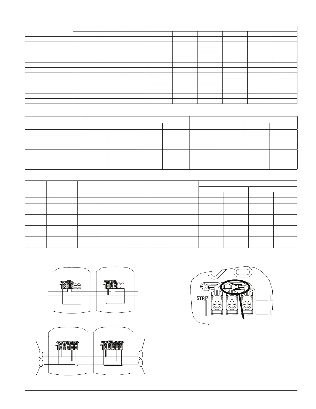
FIGURE 4. WIRING 2-WIRE PRODUCTS:
+
–
+
–
INPUT
FROM
FACP
OR
PRIOR
DEVICE
OUTPUT
TO
NEXT
DEVICE
OR EOL
A0367-01
FIGURE 5. WIRING 4-WIRE PRODUCTS:
+
–
ACP OR
FROM
+
–
+
–
+
–
OUTPUT
TO NEXT
STROBE
OR EOL
OUTPUT TO NEXT
A0366-00
FIGURE 6. SHORTING SPRING:
SHORTING SPRING
A0368-00
For 4-Wire installations, terminals 1, 2, and 3 connect to the strobe; terminals
4 and 5 connect to the horn. The horn and strobe circuits must be wired in-
dependently, and each circuit must be terminated with the appropriate EOL
device. Removal of a notification device will result in an open circuit indica-
tion on the strobe loop.
NOTE: A shorting spring is provided between terminals 2 and 3 of the mount-
ing plate to enable wiring checks after the system has been wired, but prior
to installation of the final product. This spring will automatically disengage
when the product is installed, to enable supervision of the final system. Only
available on indoor products(non K-series).
 Loading...