2 I56-2769-020R
06-10
CANDELA SELECTION
Adjust the slide switch on the rear of the product to the desired candela set-
ting in the small window on the front of the unit. All products meet the light
output profiles specified in the appropriate UL Standards. See Figures 1-3.
Use Table 1 to determine the current draw for each candela setting. For K
series products used outdoors at low temperatures, listed candela ratings must
be reduced in accordance with Table 2.
NOTE: SpectrAlert products set at 15 and 15/75 candela automatically work
on either 12V or 24V power supplies. The products are not listed for 12V op-
erating voltages when set to any other candela settings. For 4-Wire products,
total current draw may be determined by adding current draw for the specific
candela selection and the current draw for the specific horn selection use
Table 1 and Table 3.
TABLE 1. STROBE CURRENT DRAW (mA) FOR S, SC, P4 & PC4 SERIES:
Candela
8–17.5 Volts 16–33 Volts
DC FWR DC FWR
Standard Candela Range
15 123 128 66 71
15/75 142 148 77 81
30 NA NA 94 96
75 NA NA 158 153
95 NA NA 181 176
110 NA NA 202 195
11 5 NA NA 210 205
High Candela Range
135 NA NA 228 207
150 NA NA 246 220
177 NA NA 281 251
185 NA NA 286 258
TABLE 2. CANDELA DERATING:
Listed Candela
Candela rating at –40°F
(K Series Outdoor Applications Only)
15
Do not use below 32°F15/75
30
75 44
95 70
110 110
11 5 11 5
135 135
150 150
177 177
185 185
HORN SELECTION
Turn the rotary switch on the back of the product to the desired setting. For
horn and 4-wire horn/strobe products, the current draw for each setting is
listed in Table 3. For 2-wire horn/strobe products (P2 series), current draws
are listed in Tables 4 and 5. The sound output measurement for each horn
setting is shown in Table 6.
TABLE 3. HORN CURRENT DRAW (mA) FOR H, P4 & PC4 SERIES:
Pos Sound Pattern dA Out
8–17.5 Volts 16–33 Volts
DC FWR DC FWR
1 Temporal High 57 55 69 75
2 Temporal Medium 44 49 58 69
3 Temporal Low 38 44 44 48
4 Non-temporal High 57 56 69 75
5 Non-temporal Medium 42 50 60 69
6 Non-temporal Low 41 44 50 50
7 Coded High 57 55 69 75
8 Coded Medium 44 51 56 69
9 Coded Low 40 46 52 50
NOTE: In positions 7, 8, and 9, temporal coding must be provided by the NAC.
If the NAC voltage is held constant, the horn output will remain constantly on.
Positions 7, 8, and 9 are not available on 2-wire horn/strobe products.
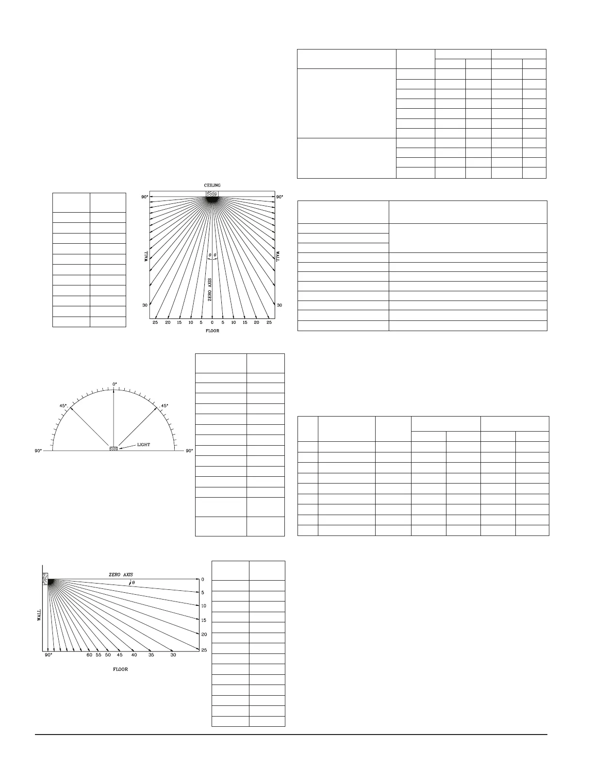
FIGURE 2. LIGHT OUTPUT -
HORIZONTAL DISPERSION
Figures 1-3 list the minimum light output requirements per UL1971.
FIGURE 3. LIGHT OUTPUT - VERTICAL DISPERSION, WALL TO FLOOR
Thisis generatedtextforfigtxt.
Degrees*
Percent of
Rating
0 100
5-25 90
30-45 75
50 55
55 45
60 40
65 35
70 35
75 30
80 30
85 25
90 25
Compound 45
to the right
24
Compound 45
to the right
24
Degrees*
Percent of
Rating
0 100
5-30 90
35 65
40 46
45 34
50 27
55 22
60 18
65 16
70 15
75 13
80 12
85 12
90 12
Degrees*
Percent of
Rating
0 100
5-25 90
30-45 75
50 55
60 45
65 35
70 35
75 30
80 30
85 25
90 25
*Tolerance of ±1 degree is permitted.
FIGURE 1. LIGHT OUTPUT - VERTICAL DISPERSION, CEILING TO WALLS
TO FLOOR
 Loading...