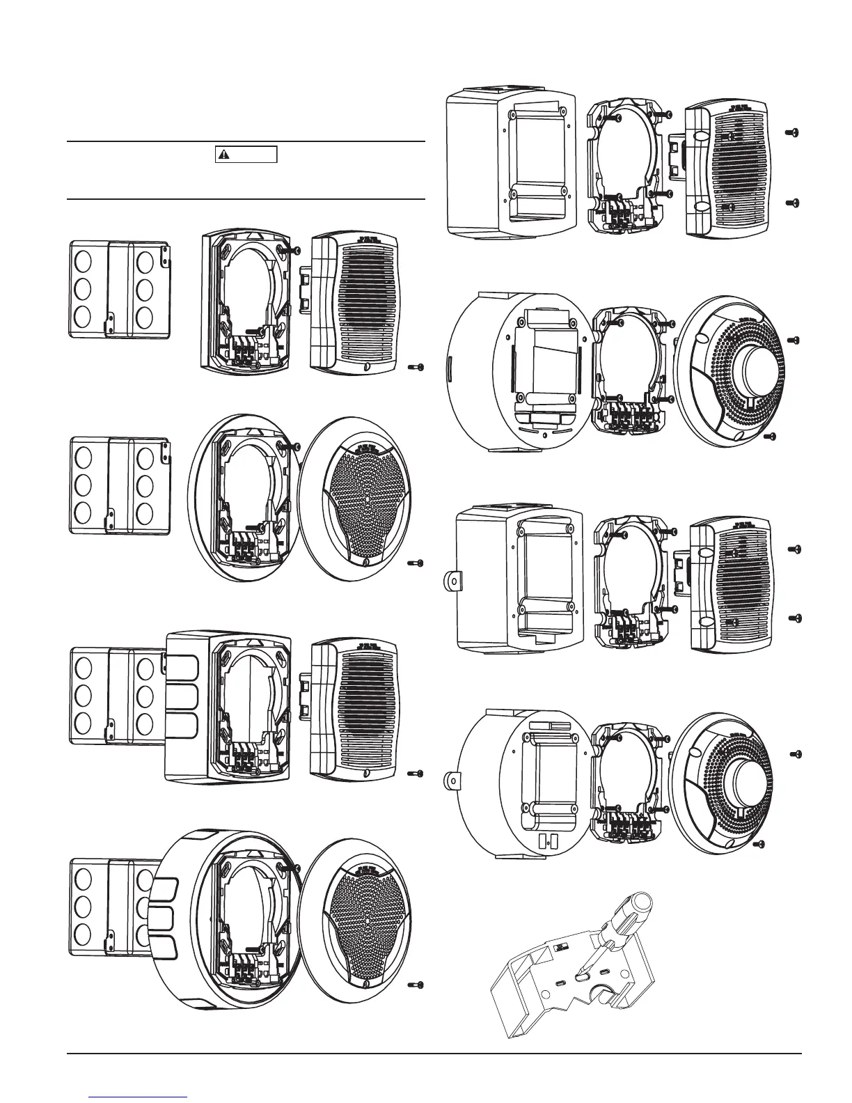
6. Attach the mounting plate to the weatherproof back box using the four
non-painted screws.
7. Follow steps 2-5 of the indoor mounting instructions to wire and attach
the product. The product must be mounted to the weather proof back
box using the painted screws (wall product has 4 screws, ceiling product
has 3 screws)
The ‘hold-in-place’ snaps are not intended to secure the product to the back
box. The product must be secured to the back box using the screws provided
FIGURE 4. WALL MOUNT PRODUCT WITH TRIM RING:
A0382-00
FIGURE 5. CEILING MOUNT PRODUCT WITH TRIM RING:
A0383-00
FIGURE 6. WALL MOUNT PRODUCT WITH BACK BOX SKIRT:
A0386-00
FIGURE 7. CEILING MOUNT PRODUCT WITH BACK BOX SKIRT:
A0385-00
SS-140-000 3 I56-3108-003R
FIGURE 8. OUTDOOR WALL MOUNT PRODUCT WITH PLASTIC
WEATHERPROOF BACK BOX:
A0384-00
FIGURE 9. OUTDOOR CEILING MOUNT PRODUCT WITH PLASTIC
WEATHERPROOF BACK BOX:
A0420-00
FIGURE 10. OUTDOOR WALL MOUNT PRODUCT WITH METAL
WEATHERPROOF BACK BOX:
A0410-00
FIGURE 11. OUTDOOR CEILING MOUNT PRODUCT WITH METAL
WEATHERPROOF BACK BOX:
A0407-00
A0424-00
FIGURE 12. FOR KNOCKOUTS USE A FLAT BLADE SCREWDRIVER.
NOTE: Place the blade along
the edge of the slot and slowly
work your way around the slot
as you strike the srewdriver.