TABLE 1. SOUND LEVELS FOR EACH TRANSFORMER POWER TAP:
UL Reverberant (dBA @ 10 ft.) SPS, SPSC SPSV, SPSCV
2W 85 89
1W 82 86
1
/2W 79 83
1
/4W 76 80
Signal levels exceeding 130% rated signal voltage can damage the speaker.
Consequently, an incorrect tap connection may cause speaker damage. This
means that if a 25V tap is selected when a 70.7V amplifier is being used,
speaker damage may result. Therefore, be sure to select the proper taps for the
amplifier voltage/input power level combination being used.
TABLE 2. STROBE CURRENT DRAW MEASUREMENTS:
Strobe Current Draw
Candela
8-17.5 Volts 16-33 Volts
DC FWR DC FWR
Standard Candela Range 15 123 128 66 71
15/75 142 148 77 81
30 NA NA 94 96
75 NA NA 158 153
95 NA NA 181 176
110 NA NA 202 195
115 NA NA 210 205
High Candela Range 135 NA NA 228 207
150 NA NA 246 220
177 NA NA 281 251
185 NA NA 286 258
CANDELA SELECTION
Adjust the slide switch on the rear of the product to position the desired can-
dela setting in the small window on the front of the unit. All products meet
the light output profiles specified in the appropriate UL Standards. Use Table 2
to determine the current draw for each candela setting. For K series products
used outdoors at low temperatures, listed candela ratings must be reduced in
accordance with Table 3.
NOTE: SpectrAlert products set at 15 and 15/75 candela automatically work
on either 12V or 24V power supplies. The products are not listed for 12V op-
erating voltages when set to any other candela settings.
TABLE 3. CANDELA DERATING:
Listed Candela Rating
Candela rating at -40°F (K Series Outdoor Applications Only)
15
Do not use
below 32°F
15/75
30
75 44
95 70
110 110
115 115
135 135
150 150
177 177
185 185
MOUNTING
Mounting Indoor Wall or Ceiling Products
1. Attach mounting plate to junction box as shown in Figures 4 and 5. The
mounting plate is compatible 4˝ x 4˝ x 2
1
/8˝ junction boxes. If using a back
box skirt or trim ring, attach the mounting plate to the skirt or trim ring and
then attach the entire assembly to the junction box (see Figures 4, 6 and 8).
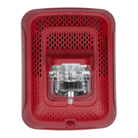
FIGURE 1. WIRING DIAGRAM:
INPUT FROM
AMPLIFIER
INPUT FROM
POWER
SUPPLY
OUTPUT TO
NEXT SPEAKER
OR EOL
OUTPUT TO
NEXT STROBE
OR EOL
(–)
(+)
(–)
(+)
(–)
(+)
(–)
(+)
A0388-00
ELECTRICAL WIRING
1. Connect the speaker as shown in Figure 1.
NOTE: Do not loop electrical wiring under terminal screws. Wires con-
necting the device to the control panel must be broken at the device
terminal connection in order to maintain electrical supervision.
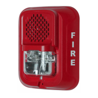
2. There are two rotary switches on the back of the product The first switch
is used to select either 25 or 70.7 volts input for the speaker portion. The
second switch is used to select the input power of
1
/4,
1
/2, 1 or 2 watts.
See diagram.
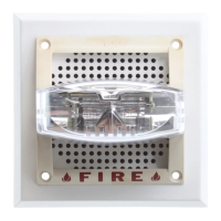
SHORTING SPRING
NOTE: Shorting springs are provided between terminals 2 and 3 and between
terminals 5 and 6 of the mounting plate to enable wiring checks after the
system has been wired, but prior to installation of the final product. These
springs will automatically disengage when the product is installed, to enable
supervision of the final system.
FIGURE 2. SHORTING SPRING
A0391-00
FIGURE 3. SPEAKER WATTAGE AND VOLTAGE SETTINGS:
C0419-00
SS-140-001 2 I56-3109-001R

 Loading...