3 I56-0003-002
10/02/2018
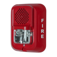
FIGURE 6. SHORTING SPRING
Spring
WIRING TERMINALS
1. Negative (-). Line in and out
2. Positive (+). Line in and out
3. Positive (+). Line in and out
Strip Guide
A0499-02
AVAILABLE POWER SETTINGS
System Sensor offers a wide range of power settings for your life safety needs,
including ¼, ½, 1, and 2W.
Sound levels data per UL 1480 can be found in Table 3.
TABLE 3. SOUND LEVELS FOR EACH TRANSFORMER POWER SETTING
Setting UL Reverberant
(dBA @10 ft)
UL Anechoic
(dBA @10 ft)
¼ W 77 77
½ W 80 80
1 W 83 83
2 W 86 86
Signal levels exceeding 130% rated signal voltage can damage the speaker.
Consequently, an incorrect tap connection may cause speaker damage. This
means that if a 25V tap is selected when a 70.7V amplifier is being used,
speaker damage may result. Therefore, be sure to select the proper taps for the
amplifier voltage/input power level combination being used.
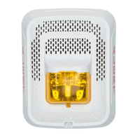
MOUNTING AND REMOVING APPLIANCE
1. Attach mounting plate to junction box using two of the provided Philips
head screws. (See Figure 7.)
2. Connect field wiring according to terminal designations (See Figure 4.)
3. If the product is not to be installed at this point, use the protective dust
cover to prevent contamination of the wiring terminals on the mounting plate.
4. To attach product to mounting plate:
a. Remove the protective dust cover.
b. Hook the tabs on the top of the product housing into the grooves on mount-
ing plate.
c. Pivot the product into position to engage the terminals on the mounting
plate. Make sure that the tabs on the back of the product housing fully en-
gage with the mounting plate.
d. Hold product in place with one hand, and secure product by tightening the
single mounting screw in the front of the product housing.
The “hold in place” snaps are not intended to secure the product to the back
box. The product must be secured to the back box using the screws provided.
Factory finish should not be altered: Do not paint!
Do not over tighten mounting plate screws; this may cause mounting plate
to flex.
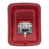
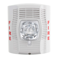
FIGURE 7. WALL SPEAKER
A0522-01
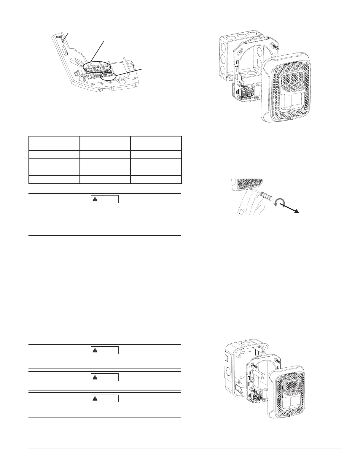
TAMPER SCREW
For tamper resistance, the standard captive screw may be replaced with a Torx
screw, ordered separately.
1. To remove the captive screw, back out the screw and apply pressure to the
back of the screw until it disengages from the housing. Replace with Torx
screw. (See Figure 8.)
FIGURE 8. TAMPER SCREW
T15 Torx
#6-32, 5/8"
SCREW-TMPR-50
A0502-01
NOTE: Wall speaker shown in this example.
INSTALLING A SURFACE MOUNT BACK BOX
1. The surface mount back box may be secured directly to the wall. Use of
grounding bracket with ground screw is optional. (See Figure 9.)
2. The wall mount box must be mounted with the up arrow pointing up. (See
Figure 10.)
3. Threaded knockout holes are provided for the sides of the box for ¾ inch
conduit adapter. Knockout holes in the back of the box can be used for ¾
inch rear entry.
4. To remove the ¾ inch knockout, place the blade of a flat-head screwdriver
along the outer edge and work your way around the knockout as you strike
the screwdriver. (See Figure 11.)
NOTE: Use caution not to strike the knockout near the top edge of the
surface mount back box.
5. V500 and V700 raceway knockouts are also provided. Use V500 for low
profile applications and V700 for high profile applications.
6. To remove the knockout, turn pliers up. (See Figure 12.)
FIGURE 9. SURFACE MOUNTING ON WALL
A0523-01
 Loading...