2 I56-0003-002
10/02/2018
WIRING AND MOUNTING
All wiring must be installed in compliance with the National Electric Code
and the local codes as well as the authority having jurisdiction. Wiring must
not be of such length or wire size which would cause the notification appli-
ance to operate outside of its published specifications. Improper connections
can prevent the system from alerting occupants in the event of an emergency.
Wire sizes up to 12 AWG (2.5 mm²) may be used with the mounting plate. The
mounting plate ships with the terminals set for 12 AWG wiring.
Make wire connections by stripping about
3
/
8
" of insulation from the end of
the wire. Then slide the bare end of the wire under the appropriate clamping
plate and tighten the clamping plate screw.
See Figure 4 for wiring terminals and strip guide reference.
1. Connect the speaker. (See Figure 4.)
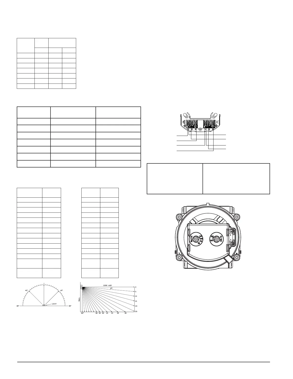
2. There are two rotary switches on the back of the product. The first switch
is used to select either 25 or 70.7 volts input and the second switch is used to
select the input power of ¼, ½, 1 or 2 watts. (See Figure 5.)
FIGURE 4. WIRING DIAGRAM AND WIRING TERMINALS
(-)
(+)
(-)
(+)
(-)
(+)
(-)
(+)
From FACP
OUTPUT
To Next Device or EOL
From Amplifier
INPUT
To Next Device or EOL
A0519-01
Wiring Terminals
1. Negative (-). Line in and out
2. Positive (+). Line in and out
3. Positive (+). Line in and out
NOTE: Do not loop electrical wiring un-
der terminal screws. Wires connecting
the device to the control panel must be
broken at the device terminal connec-
tion in order to maintain electrical su-
pervision.
FIGURE 5. SPEAKER WATTAGE AND VOLTAGE SETTINGS
A0419-01
SHORTING SPRING FEATURE
System Sensor notification appliances come with a shorting spring that is pro-
vided between terminals 2 and 3 of the mounting plate to enable system con-
tinuity checks after the system has been wired, but prior to installation of the
final product. (See Figure 6.) This spring will automatically disengage when
the product is installed, to enable supervision of the final system.
CURRENT DRAW RATINGS
For the strobe, the current draw for each setting is listed in Table 1.
TABLE 1. WALL-MOUNT STROBE CURRENT DRAW (mA)
Candela
8-17.5
Volts
16-33 Volts
DC DC FWR
15 88 43 60
NOTE: Products set at 15 and 30
candela automatically work on ei-
ther 12V or 24V power supplies.
The products are not listed for
12V DC operation when set to any
other candela settings.
30 143 63 83
75 - 107 136
95 - 121 155
110 - 148 179
135 - 172 209
185 - 222 257
TABLE 2. CANDELA DE-RATING BY LENS COLOR
Wall Candela
Setting
Private Mode Emergency Warning
15 15 12
30 30 24
75 75 60
95 95 75
110 110 85
135 135 105
185 185 145
FIGURE 2. WALL LIGHT OUTPUT – FIGURE 3. VERTICAL
HORIZONTAL DISPERSION DISPERSION, WALL TO FLOOR
Degrees*
Percent of
Rating
Degrees*
Percent of
Rating
0 100 0 100
5-25 90 5-30 90
30-45 75 35 65
50 55 40 46
55 45 45 34
60 40 50 27
65 35 55 22
70 35 60 18
75 30 65 16
80 30 70 15
85 25 75 13
90 25 80 12
Compound 45
to the left
24 85 12
Compound 45
to the right
24 90 12
A0467-00
A0469-00
*Tolerance of ±1 degree is permitted.
Thisisgenerated textforfigtxt.
 Loading...