8
206268 Systemair Sverige AB
KBT EC
For KBT 160EC
Line Connection Colour Assignment/function
1 L black Mains 50/60 Hz, phase
N blue Mains 50/60 Hz, neutral
PE green/yell
ow
Protective earth
NC white1 Alarm relay, break for failure
COM white2 Alarm relay, COMMON
Line Connection Colour Assignment/function
2 +10V red Voltage output +10V max 1.1 mA
0-10V/PWM yellow
Control input (impendence 100 k)
GND blue Protective earth
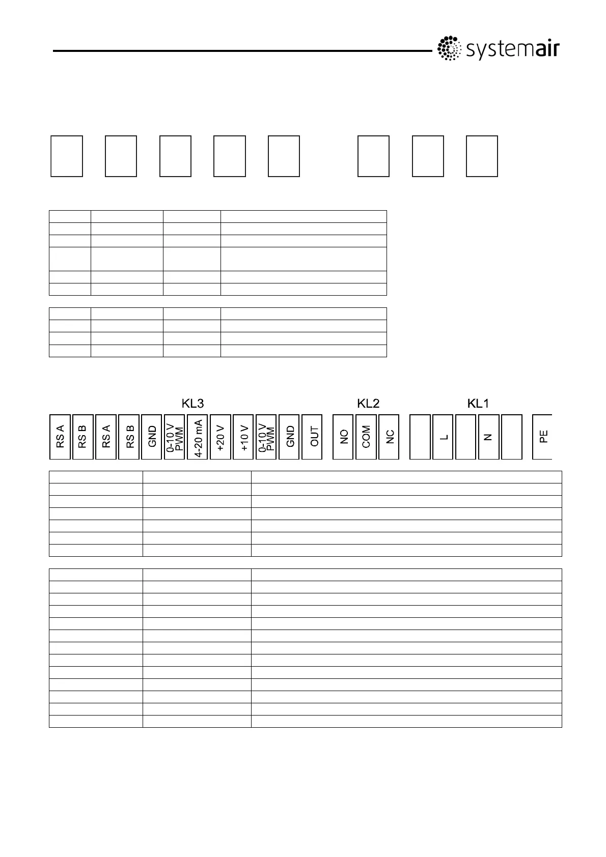
For KBT 180-200 EC
Connector Connection Assignment/function
PE PE Protective earth
KL1 N Mains 50/60 Hz, neutral
L Mains 50/60 Hz, phase
KL2 NC Alarm relay, brake for failure
COM Alarm relay, COMMON (2 A, 250 VAC, AC1)
NO Alarm relay, make for failure
Connector Connection Assignment/function
KL3 OUT Master output 0-10V max 3 mA
GND GND
0-10 V / PWM Control / Actual value input (Impedance 100k)
+10 V Supply for external potentiometer, 10 VDC (+10%) max 10 mA
+20 V Supply for external sensor, 20 VDC (±20%) max 50 mA
4-20 mA Control / Actual value input
0-10 V /PWM Control / Actual value input
GND GND
RSB RS485 interface for ebmBUS; RS B
RSA RS485 interface for ebmBUS; RS A
RSB RS485 interface for ebmBUS; RS B
RSA RS485 interface for ebmBUS; RS A
L
N
PE
NC
COM
+10V
GND
0-10V
PWM
Line 1
Black Blue Green/yellow White1 White2 Red Yellow Blue
Line 2

 Loading...