Do you have a question about the SystemAir K EC Series and is the answer not in the manual?
Wiring diagrams for internal and external potentiometer connections for K EC, RS 30-15 EC, RS 40-25 EC.
Wiring diagrams for internal and external potentiometer for KVK Silent 125-160EC.
Description of terminal connections for KVK Silent 125-160EC, including output and input signals.
Wiring diagram for internal potentiometer connection for TFSR/TFSK EC.
Wiring diagram for external potentiometer connection for TFSR/TFSK EC.
Wiring diagram for internal potentiometer connection for KVK Slim 100-160 EC.
Wiring diagram for external potentiometer connection for KVK Slim 100-160 EC.
Wiring diagrams for internal and external speed settings for KD EC 315, 355.
Explanation of alarm terminals and external control options for KD EC, RS EC, RSI EC.
Description of terminal connections for RS 50-25 EC, including GND, control input, and alarm.
Description of terminal connections for RS 60-35 EC, RSI 60-35 EC, including interface and control inputs.
Wiring diagrams for internal and external potentiometer, and control functions.
Wiring diagrams for internal and external potentiometer, and control functions.
Description of line 1 and line 2 connections for KBT 160EC, including mains, PE, and control signals.
Details on connectors KL1, KL2, KL3 and their assignments for KBT 180-200 EC.
Terminal assignments for class 3 connections (0-10V, 4-20mA, voltage supplies) for KBT 225-250 EC.
Terminal assignments for class 2 connections (alarm relay) for KBT 225-250 EC.
Terminal assignments for class 1 connections (net connections L1, L2, L3, PE) for KBT 225-250 EC.
Wiring diagram for external potentiometer for KV DUO 150-315 EC.
Wiring diagram for external potentiometer for KV DUO 400 EC.
Wiring diagram for external potentiometer for KV DUO 500-630 EC.
Performance chart showing pressure vs. flow for K EC 100 at different voltage settings.
Performance chart showing pressure vs. flow for K EC 125 at different voltage settings.
Performance chart showing pressure vs. flow for K EC 150 at different voltage settings.
Performance chart showing pressure vs. flow for K EC 160 at different voltage settings.
Performance chart showing pressure vs. flow for K EC 200 at different voltage settings.
Performance chart showing pressure vs. flow for K EC 250 at different voltage settings.
Performance chart showing pressure vs. flow for K EC 315M at different voltage settings.
Performance chart showing pressure vs. flow for K EC 315L at different voltage settings.
Performance chart showing pressure vs. flow for KVK Silent 125 EC at different voltage settings.
Performance chart showing pressure vs. flow for KVK Silent 160 EC at different voltage settings.
Performance chart showing pressure vs. flow for TFSR/TFSK EC 160 at different voltage settings.
Performance chart showing pressure vs. flow for TFSR/TFSK EC 200 at different voltage settings.
Performance chart showing pressure vs. flow for KVK Slim 100 EC at different voltage settings.
Performance chart showing pressure vs. flow for KVK Slim 125 EC at different voltage settings.
Performance chart showing pressure vs. flow for KVK Slim 160 EC at different voltage settings.
Performance chart showing pressure vs. flow for KD EC 315E at different voltage settings.
Performance chart showing pressure vs. flow for KD EC 355E at different voltage settings.
Performance chart showing pressure vs. flow for KD EC 400E at different voltage settings.
Performance chart showing pressure vs. flow for prio 450 3~ EC at different voltage settings.
Performance chart showing pressure vs. flow for prio 500 3~ EC at different voltage settings.
Performance chart showing pressure vs. flow for RS 30-15 EC at different voltage settings.
Performance chart showing pressure vs. flow for RS 40-20 EC at different voltage settings.
Performance chart showing pressure vs. flow for RS 50-25 EC at different voltage settings.
Performance chart showing pressure vs. flow for RS, RSI 60-35 EC at different voltage settings.
Performance chart showing pressure vs. flow for RS, RSI 70-40 EC at different voltage settings.
Performance chart showing pressure vs. flow for RS, RSI 80-50 EC at different voltage settings.
Performance chart showing pressure vs. flow for RS, RSI EC 100-50 at different voltage settings.
Performance chart showing pressure vs. flow for KBT 160EC at different voltage settings.
Performance chart showing pressure vs. flow for KBT 180EC at different voltage settings.
Performance chart showing pressure vs. flow for KBT 200EC at different voltage settings.
Performance chart showing pressure vs. flow for KBT 225EC at different voltage settings.
Performance chart showing pressure vs. flow for KBT 250EC at different voltage settings.
Performance chart showing pressure vs. flow for KV DUO 150 EC at different voltage settings.
Performance chart showing pressure vs. flow for KV DUO 250 EC at different voltage settings.
Performance chart showing pressure vs. flow for KV DUO 315 EC at different voltage settings.
Performance chart showing pressure vs. flow for KV DUO 400 EC at different voltage settings.
Performance chart showing pressure vs. flow for KV DUO 500 EC at different voltage settings.
Guide for screw type I for mounting K EC 100.
Guide for screw type II for mounting K EC 125.
Guide for screw types I + II for mounting K EC 160.
Guide for screw types I + II for mounting K EC 200.
Guide for screw types I + II for mounting K EC 250.
Guide for screw types I + II for mounting K EC 315 M/L.
Details of the manufacturer, Systemair Sverige AB, including address and contact information.
Confirmation that specified product categories comply with EU directives and regulations.
List of EU directives and regulations that the products comply with.
List of harmonized standards applied to the products in relevant parts.
Date and location of the EU Declaration of Conformity.
Name and title of the signatory for the EU Declaration of Conformity.
Instructions for installation, electrical connection, and commissioning by authorized personnel.
Details on the factory preset integral potentiometer and its adjustment for motor rpm.
Explanation of the tach output terminal (No. 1) for RPM counting and control signals.
Checks to perform before initial operation, including electrical connection and safety devices.
Procedures for cleaning, servicing, and repairing the fan, including safety precautions.
Guidelines for disposing of the product according to WEEE directive and recycling packaging materials.
| Frequency | 50/60 Hz |
|---|---|
| Protection class, motor | IP54 |
| Casing material | Galvanized steel |
| Installation | Duct mounting |
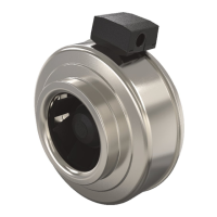
| Product Series | K EC |
| Category | Fan |
| Impeller | Backward curved |
| Motor type | EC (Electronically Commutated) motor |
| Speed control | 0-10V |
| Efficiency Class | IE5 |
| Mounting | Duct |
| Sound Power Level | Varies by model |
| Applications | Ventilation systems |