EasyManuals Logo

SystemAir SAVE VTR 150/K Installation Instructions

SystemAir SAVE VTR 150/K
18 pages
To Next Page IconTo Next Page
To Previous Page IconTo Previous Page
Page #13 background imageLoading...
Page #13 background image
Electrical connections |
9
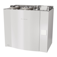
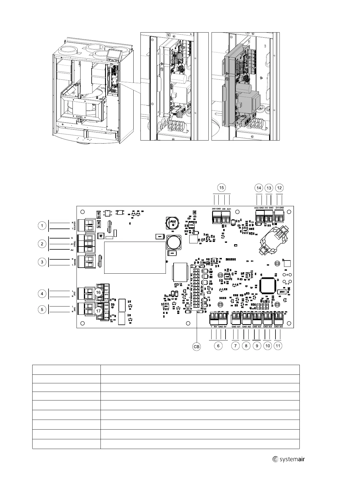
Fig. 4 Main circuit board position
7.1 Main circuit board layout
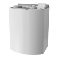
The SAVE VTR 150/K is equipped with built-in regulation and internal wiring.
Fig. 5 Main circuit board connections
Position Description
CB
Connection to the external connection box
1
Terminals for a heater
2
Terminals for a TRIAC
3
Terminals for the mains power supply
4
Terminals for power supply of extract air fan
5
Terminals for power supply of supply air fan
6
Terminals for internal relative humidity/temperature sensor
7
Analog input 1 Outdoor air sensor
254494 | v01

Other manuals for SystemAir SAVE VTR 150/K

Questions and Answers:

Question and Answer IconNeed help?

Do you have a question about the SystemAir SAVE VTR 150/K and is the answer not in the manual?

SystemAir SAVE VTR 150/K Specifications

General IconGeneral
BrandSystemAir
ModelSAVE VTR 150/K
CategoryAir Conditioner
LanguageEnglish

Related product manuals