6Externalconnections
See5.5Electricalconnectionsandtheenclosedwiringdiagram,howtoconnecttheelectricalcables.
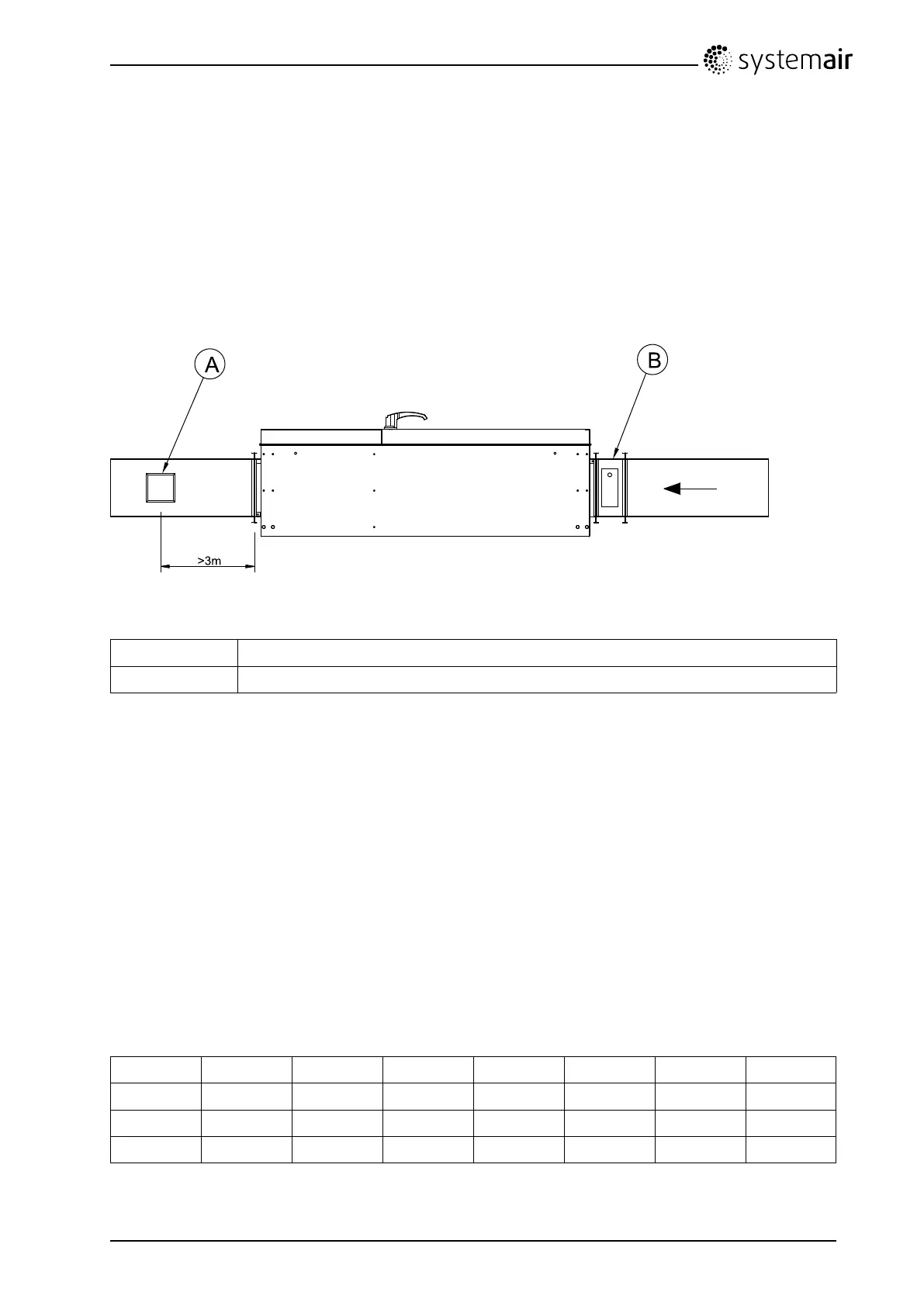
6.1Temperaturesensor,supplyairandoutdoorair
damper
Attachedductsensorissupposedtobemountedapproximately3metersfromtheunit(posA).
Fig.9Tempsensoranddamper
A
Sensor,supplyair
B
Motorizeddamper,outdoorair(Accessories)
Theoutdoorairdamper(Supplyvoltage24VAC,Springreturn)areusedtoavoidcoldairtocomeintothe
buildingwhentheunitarestoppede.g.duringnight.
Thedamperisalsopreventingthehotwaterbatteryfromfreezingbyclosingwhenthereturningwaterin
thebatteryisbelowasettemperature,+8°C,alternativelyifthesupplyairtemperaturedropsbelowa
settemperature(adjustable).
6.2Extractfan
ExtractfancanbeconnectedtotheunitandbeoperatedparallelwiththeTAsupplyfan.
Theextractfanmustbe1-phase(voltagecontrollable)uptoTAsize1400and3-phase(voltage
controllable)forTAsize2000andlarger.
Theextractfanmusthaveanintegratedthermalswitchtoprotectthefanfromoverheating.
Table1:Availablecurrentforexternalextractfan(A)
45065011001400200030004500
230V,1N0,70,953,52,6
---
400V,3N
----
2,82,04,3
230V,3N
----
4,83,57,4
TA450-4500Installationinstructions
132615
20
SystemairSverigeAB
 Loading...