Topvex TR800, TR1300, TR1800, TR4000
Operation and Maintenance Instructions
Systemair Inc.
8
3 Interface Description
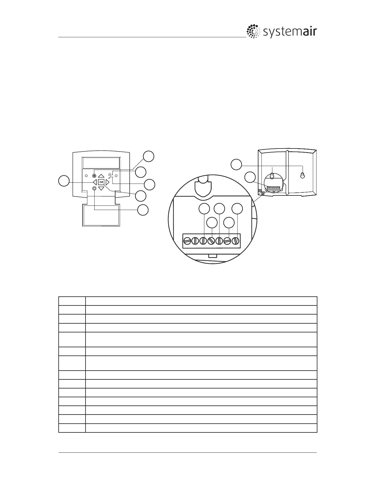
3.1 Control Panel
The SCP control panel is delivered with a 32.8 Ft. (10 m) cable that is connected to the panel and with a
fast coupling contact, connected to the Topvex unit. The contact is connected to the Corrigo controller in
the electrical connection box (pos.1, gure 3-4-5). The cable can be unscrewed in the back of the control
panel (gure 6)
3.1.1 Operating the Control Panel
Fig. 6 The control panel
Position Explanation
1 Alarm button: Gives access to the alarm list.
2 Alarm LED: Indicates alarm by ashing red light.
3 Write LED: Indicates by ashing yellow light that parameters can be set or changed.
4 OK button: Press this button to be able to change or set parameters whenever possible. Also
used to move between chargeable parameters in one dialogue window frame.
5 Cancel button: Used to abort a change and return to the initial setting.
6 Right/Left & Up/Down buttons: Used to move up, down, left & right in the menu tree. Up/Down
buttons are also used to increase values when setting or changing parameters.
7 Mounting holes
8 Connection block.
9 Connection to yellow cable.
10 Connection to orange cable.
11 Connection to red cable.
12 Connection to brown cable.
13 Connection to black cable
Table 4: Description of Control panel and wire connection
10 12
11 13
8
7
9
4
3
1
2
6
5
 Loading...