Topvex TR800, TR1300, TR1800, TR4000
Operation and Maintenance Instructions
Systemair Inc.
6
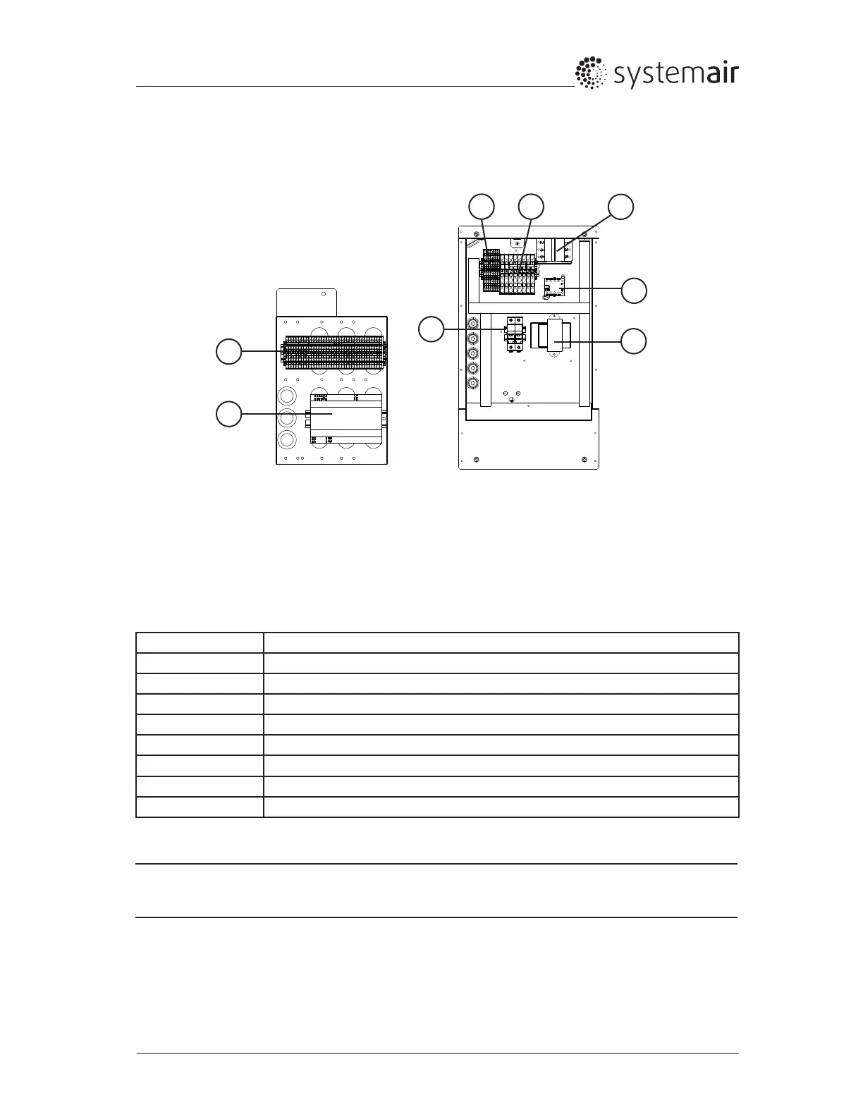
Topvex TR800-1800 are equipped with a built in controller and internal wiring (Figure 4).
Fig. 4 Electrical components Topvex TR800-1800 HW
Position Description
1 Controller E-28 (UC)
2 Transformer 208-230/24VAC (TR24)
3 Terminals for internal and external components (TB3)
4 Terminals for internal wiring (TB2)
5 Terminals for main power voltage to the unit (TB1)
6 Contactor (K1) On/Off rotor motor
7 Automatic fuse (AS1)
8 Fuse holders F1 and F2
Table 3: Description of electrical components Topvex TR800-1800 HW
Note:
For pre-heater components, please refer to the “Pre-Heater installation instructions (420353).
2.3.2 Electrical Connection Box Topvex TR800-1800 HW
2
1
3
6
4 5
7
8
 Loading...