_________________________________________________________________________________________________________
VR 300 ECV/B Installation description
206552 (12-12-2012)
12 Systemair AB
Electrical connection
The unit
The VR 300 ECV/B units are supplied with apx. 1m cable and plug for 10A, 230V, single phased earthed
connection. The electrical connection to the cooker hood is done through connection plugs (fig. 10)
situated on the bottom plate of the unit. The 3 pole connection plug (pos. 1, fig. 10) is used for the mains
supply of the cooker hood light and the 4 pole connection plug is used for the speed control signal.
In case a cooker hood is not used and the speed control is done by an external speed regulator the 3
pole connection plug (pos 1, fig. 10) is not used.
See also the wiring diagram, which is enclosed with the unit.
1
2
Fig. 10
Speed control
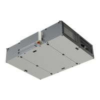
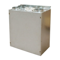
The VR 300 ECV/B (pos 1, fig. 11) can alternatively be controlled from a wall mounted 3 step speed
regulator (pos 2, fig. 11) or from a cooker hood where the speed control is integrated in cooker hood front.
If a separate 3-step speed regulator is used a 3-wire cable needs to be connected to the speed
regulator (fig.12) At the end of that cable a 4 pole male plug, type Ensto NAC41SH.W can be
applied in order to fit the corresponding connector (Ensto NAC42SH.W) on the VR 300 ECV/B. Make sure
that the cable colors correspond to each other when the two connectors are joined.
Check the enclosed wiring diagram for more detailed information.
1
2
3
2
Position Description
1 Air handling unit VR 300 ECV/B
2 3-step speed regulator
3 Control signal connection plug
Fig. 11
 Loading...