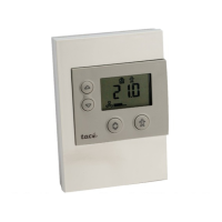
Do you have a question about the t.a.c. Satchwell Climatronic CSC5252 and is the answer not in the manual?
Controller placement requirements regarding environment and clearance.
Guidelines for safe and effective wiring, including screening and separation.
List of sensors compatible with the CSC controller and type mixing rules.
Procedure for replacing sensors and selecting the correct type.
How to use room sensors to influence flow temperature and avoid issues.
Step-by-step procedure for initial setup and configuration.
Details on Room Influence, Night Set Back, and Frost Logic operations.
Procedure to restore factory default settings and auto-configure sensors.
Controlling flow temperature using a 3-port mixing valve based on outside temperature.
Electrical connection diagrams for compensated valve control.
Controlling flow temperature by switching the boiler based on outside temperature.
Electrical connection diagrams for compensated boiler control.
Application for controlling secondary water temperature in district heating.
Electrical connection diagrams for district heating applications.
Using manual overrides for actuator control in mains output applications.
Using manual overrides for actuator control in 24VAC output applications.
Using the rotary switch to select and apply manual override functions.
Explanation of the controller's operating modes: Review, Quick Set, and Fine Tune.
Overview of display functions, parameter review, and Quick Set mode access.
Detailed steps for entering and leaving the Quick Set Mode.
General method for adjusting parameter values within Quick Set Mode.
Procedure to program the internal clock and day for CSC 5352.
Instructions for using overlay cards with the Fine Tune mode.
Steps for accessing and exiting the advanced Fine Tune Mode.
Adjusting the economy mode to shut down the plant at high outside temperatures.
Instructions for replacing the internal battery to maintain clock function.
Overview of manual override functions controllable via the rotary switch.
Read-only display mode for viewing various controller parameters.
Procedure to access and use the Quick Set Mode for basic settings.
Steps for accessing and exiting the Fine Tune Mode for advanced settings.
Default programmed time schedule for daily ON/OFF periods.
| Brand | t.a.c. |
|---|---|
| Model | Satchwell Climatronic CSC5252 |
| Category | Thermostat |
| Language | English |