TAC Xenta 511 and 911 Handbook 2 TAC Xenta 511
TAC AB, 16 May 2003 0-004-7870-0 (EN), 15 (32)
2.4 Operation and Service
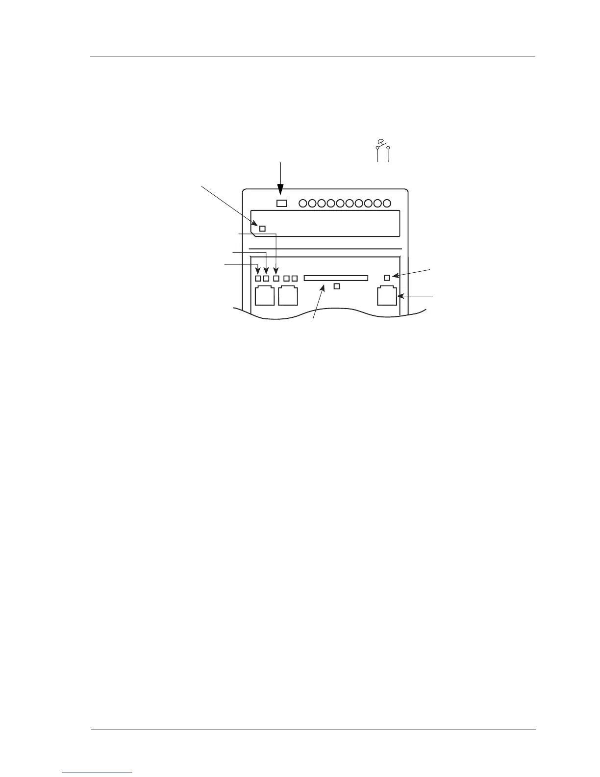
2.4.1 LED Indicators
LON Neuron status
Off Normal Mode
Red, blinking Unconfigured Node
Red, steady Hardware Fault
Fail-safe state
Shorting terminals Fail-safe 9 and 10 will put the unit in the “fail-safe”
state. This may be used in an emergency if the system program keeps
halting.
The position of the switch is noted directly after powering on.
Overall status indicator
Green, steady Normal Mode
Green, blinking Start Mode
Red, steady Fail-safe Mode (see description above)
Red, blinking Unit Error
2.4.2 Service Utilities
System service functions are available using the web browser and are
located under the Utilities menu. They are primarily intended to provide
technical information about the system and its status and can be printed
to a file or a printer.
System Info
MMC
10Base-T
A RS232 B
LON
Fail-
safe
Rx/Tx
9 10
TAC Xenta 511 status indicators
 Loading...