Mounting instructions
RVT 50 B, RVT 50 C and
RVT 60 B
The RVT 50 B and RVT 50 C thermostat
should because of heat interference be fitted
horizontally on the valve. Install the valve
and the thermostat in such a way that the
thermostat sensor is influenced by air
temperature representative of the room
concerned. Where abnormal influence of
heat or cold cannot be avoided, then RVT 60
B should be used.
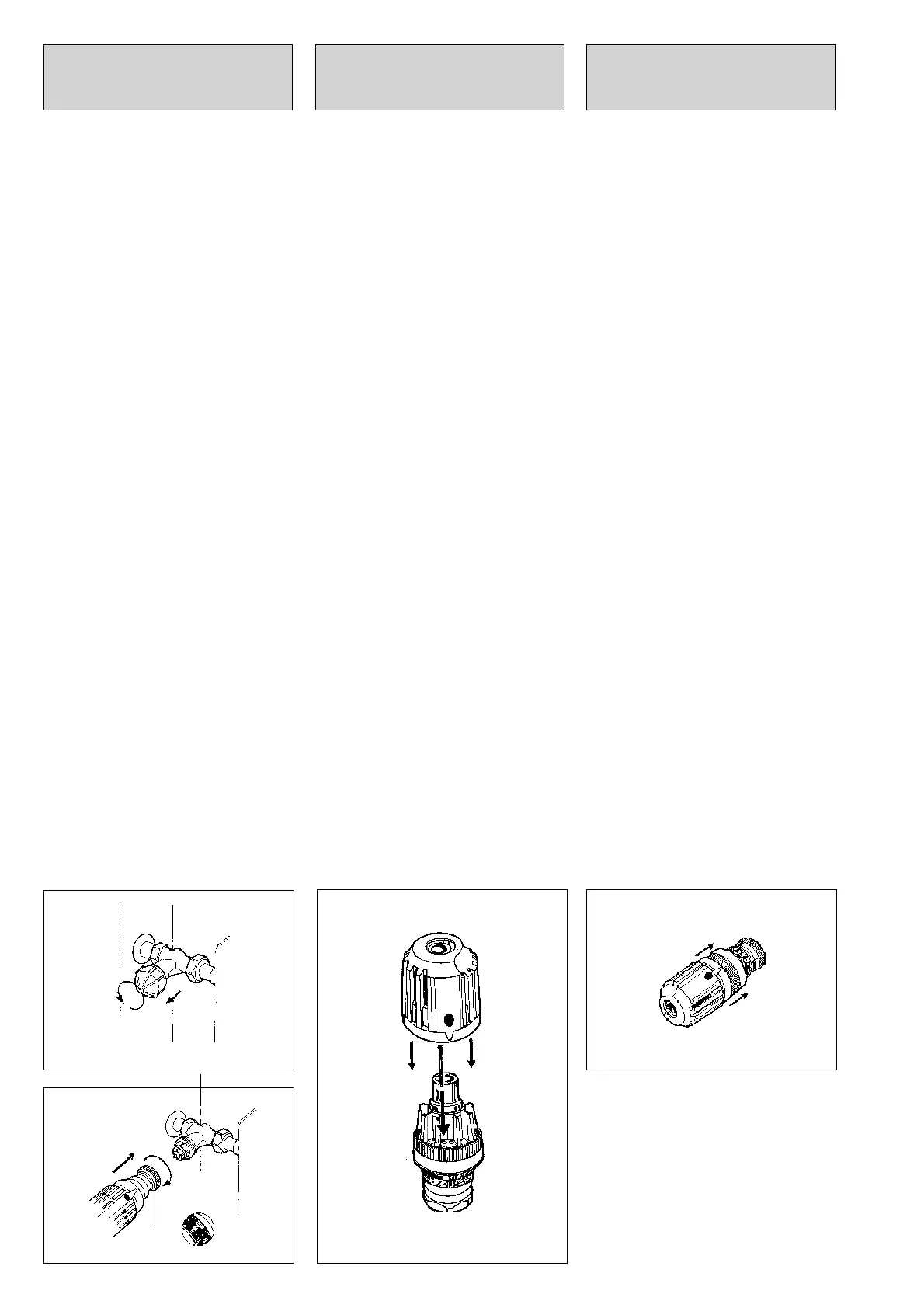
1. Fitting the thermostat.
a) Unscrew the protective cap from the valve
(save protective cap).
b) Secure the thermostat to the valve so that
the index mark on the insulator is clearly
visible.
2. Limiting the temperature range
upwards.
Set the thermostat to the desired level.
Remove the handwheel. Insert a stop pin in
the nearest hole to the right of the set figure.
3. Limiting the temperature range
downwards.
The same procedure as in paragraph 2 but
the pin is now placed in the nearest hole to
the left of the set figure.
4. Locking the thermostat at the desired
temperature.
The same procedure as in paragraph 2 but
with a stop pin located on each side of the
set figure.
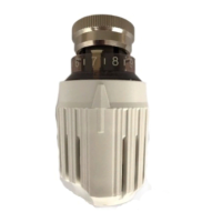
5. Marking the set value. The setting giving
the desired room temperature can be marked
by removing the handwheel and locating it so
that the "memory point" is opposite the
desired figure.
6. Fitting a separate sensor with
capillary tubing .
Place the sensor in such a way that it is not
influenced by heat from the radiator, heating
pipes or is subjected to direct sun radiation
or draughts from windows and doors. Press
the sensor firmly into the retainer and then fit
the casing. Fix the capillary tube to the wall
with the clips supplied.
1b
Instructions de montage des
têtes thermostatiques
RVT 50 B, RVT 50 C et RVT 60 B
Les têtes thermostatiques RVT 50 B et 50 C
doivent toujours être montées horizontale-
ment sur le robinet, par rapport au radiateur.
Il faut veiller à ce que le détecteur de la tête
thermostatique soit placé à un endroit
représentatif de la température ambiante de
la pièce. Si on ne peut pas éviter l'influence
d'une source de chaleur ou de froid sur
l'élément sensible incorporé, il faut utiliser la
tête thermostatique RVT 60 B avec détecteur
à distance.
1. Montage de la tête thermostatique
a) Dévisser le capuchon de protection du
robinet. Il faut conserver ce capuchon car il
sera utile lors d'un éventuel démontage du
radiateur.
b) Monter la tête thermostatique sur le
robinet de manière à ce que l'index (voir
figure 1b) soit bien visible. Assurer une
bonne fixation de la tête en serrant
convenablement l'écrou.
2. Limitation maxi de la plage de réglage.
Positionner le thermostat à la valeur maxi
souhaitée. Retirer la poignée. Enfoncer une
goupille de blocage dans le trou situé
immédiatement à droite du chiffre
sélectionné.
3. Limitation mini de la plage de réglage.
Même procédure que pour la limitation maxi,
mais cette fois-ci la goupille doit être
enfoncée immédiatement à gauche du chiffre
sélectionné.
4.Blocage du thermostat à la température
de consigne. On procède de la même façon
qu'au point 2, mais en plaçant une goupille
de chaque côté du chiffre sélectionné.
5. Repérage de la position de réglage.
La position de réglage correspondant à la
température souhaitée est facilement
repérable, il suffit de positionner le "point-
repère" en face du chiffre sélectionné.
6. Montage du détecteur à distance et du
tube capillaire. Choisir pour le détecteur un
emplacement où il ne sera pas soumis à
l'influence directe du soleil, des courants
d'air, du corps de chauffe ou d'une conduite
d'eau chaude. Le tube capillaire se fixe au
mur à l'aide des attaches qui sont jointes à la
livraison. Fixer le détecteur et appliquer le
couvercle sur le boîtier.
Montageleitung für RVT 50 B,
RVT 50 C und RVT 60 B
Die Thermostatköpfe RVT 50 B und 50 C
werden stets waagerecht am Ventil und
rechtwinklig oder parallel zur Wand montiert.
Ventil und Thermostat so montieren, daß der
Fühlkörper des Thermostaten von der für
den Raum repräsentativen Lufttemperatur
beeinflußt wird.Wenn eine außergewöhn-
liche Beeinflussung durch Wärme oder Kälte
unvermeidbar ist, den RVT 60 B verwenden.
Der RVT 60 B kann in beliebiger Lage am
Ventil montiert werden.
1. Montage des Thermostaten.
a) Schutzkappe vom Ventil abschrauben und
zur Absperrung des Ventils bei der Demon-
tage des Heizkörpers aufbewahren.
b) Thermostatkopf so am Ventil befestigen,
daß die Skala gut ablesbar ist.
2. Maximale Temperaturbegrenzung.
Den Thermostatkopf auf den gewünschten
Wert einstellen. Den Drehgriff entfernen.
Einen Anschlagstift in das Loch rechts von
der eingestellten Ziffer stecken und bis zum
Anschlag eindrücken.
3. Minimale Temperaturbegrenzung.
Wie unter 2, jedoch Stift ins Loch links von
der eingestellten Ziffer eindrücken.
4. Sicherung der Thermostateinstellung
auf gewünschte Temperatur.
Wie unter 2, aber Stifte auf beiden Seiten der
eingestellten Ziffer eindrücken.
5. Markierung des eingestellten Wertes.
Die Einstellung für die gewünschte Raum-
temperatur kann man markieren, in dem der
Drehgriff abgezogen und so wieder auf-
gesteckt wird, daß der "Markierungspunkt "
genau auf die Ziffer für die gewünschte
Raumtemperatur zeigt.
6. Montage des Fernfühlers mit Kapillar-
rohr. Den Halter für den Fühlkörper so
befestigen, daß er nicht durch Wärme von
Heizkörper oder Rohrleitung beeinflußt wird.
Den Fühlkörper mit der Kappe in die
Halterung drücken und das Kapillarrohr mit
den mitgelieferten Klammern an der Wand
befestigen. Darauf achten, daß der Fühl-
körper nicht direkter Sonnenbestrahlung oder
Zugluft von Fenstern und Türen ausgesetzt
wird.
1a 5
2-3-4
 Loading...