Do you have a question about the TAC Xenta 422 and is the answer not in the manual?
Manual structure and where to find information.
Definitions of terms used in the manual.
Explains special text markings for warnings, cautions, notes, and hints.
Lists other relevant documents for TAC Xenta 400 I/O modules.
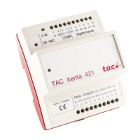
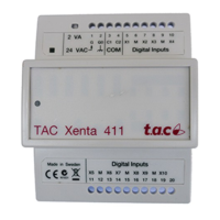
Overview of TAC Xenta hardware units: controller, expansion modules, and operator panel.
Describes how I/O modules can be used in various network configurations.
Overview of common features: terminals, indicators, and service pin.
Explains the use of the first four screw terminals for power and network communication.
Details the service pin and LED indicators (red/green) on the I/O modules.
Covers the features, terminals, and indicators of the TAC Xenta 411/412 modules.
Describes the digital input/output capabilities, terminals, and override switches.
Explains how to mount controllers and I/O modules on DIN rails or walls.
Details electrical installation aspects and safety considerations.
Covers installation standards (CAT III) and safety compliance for connected equipment.
Instructions for mounting terminal parts and connecting cables to modules.
| Analog Inputs | 4 |
|---|---|
| Analog Outputs | 2 |
| Communication | RS-485 |
| Operating Temperature | 0 to 50 °C (32 to 122 °F) |
| Communication Protocol | TAC Xenta protocol, Modbus RTU |
| Protection Class | IP20 |
| Series | Xenta |
| Supply Voltage | 24 V DC |
| Protocol | Modbus RTU |