Do you have a question about the Taco Comfort Solutions SR503-4 and is the answer not in the manual?
Explains circulator energization and boiler start signal for cold start applications.
Details how Zone 3 priority impacts other zones' operation.
Covers auto-reset for priority zones after prolonged calls.
Instructions for jumper connection between ZC and ZR for boiler control.
Procedure for connecting 120 VAC power input to N and H terminals.
Advises on the potential need for a resistor between W and C terminals.
Essential safety precautions and wire gauge recommendations for wiring.
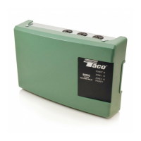
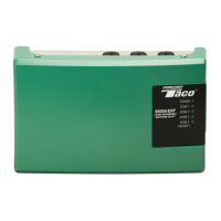
Lists product details including number, voltage, load, and dimensions.
Explains boiler signal based on temperature and circulator energization.
Details how Zone 3 priority impacts other zones' operation.
Covers auto-reset for priority zones after prolonged calls.
Instructions for jumper removal and connecting ZC/ZR to aquastat.
Procedure for connecting 120 VAC power input to N and H terminals.
Warns about risks of incorrect wiring and secondary power sources.
Addresses digital thermostat issues and zone heating problems.
Covers repair, replacement, responsibilities, exclusions, and liability limitations.
The Taco SR503-4 Switching Relay is a control device designed to manage heating systems, particularly those with multiple zones and either cold start or tankless coil boilers. Its primary function is to energize appropriate circulators and signal the boiler to start when a thermostat calls for heat.
The SR503-4 acts as an interface between thermostats, circulators, and the boiler. It features three zones, with one zone designated as a priority zone. When a thermostat in any zone calls for heat, the relay energizes the corresponding circulator. For cold start boiler applications, it also activates an isolated end switch (terminals X and X) to start the boiler. In tankless coil boiler applications, the relay signals the boiler to start via terminals ZC and ZR, but the circulator is only energized when the boiler temperature is above a set low limit.
The device offers a priority feature for Zone 3. When Zone 3 is set to priority and calls for heat, all other zones will temporarily cease operation until Zone 3's heating demand is satisfied. If Zone 3 is not configured for priority, all zones operate independently, allowing for simultaneous heating in multiple areas.
To prevent a single priority zone from monopolizing the boiler for extended periods, the SR503-4 includes a priority protection mechanism. If the priority zone (Zone 3) calls for heat continuously for more than one hour, the relay will temporarily override the priority setting and return power to all other zones, allowing them to function independently. Once the priority zone's demand is met, the control's auto-reset feature reactivates, and Zone 3 regains its priority status for up to one hour from its next call for heat. This ensures that other zones are not left without heat for too long.
| Type | Relay |
|---|---|
| Number of Zones | 4 |
| Voltage | 24V AC |
| Input Voltage | 24V AC |
| Thermostat Input | 24VAC |
| Switching | SPST |
| Number of Poles | 1 |
| Terminal Type | Screw Terminals |
| Category | Relays |