EasyManua.ls Logo

Taco SR501-HC-4

Default Icon
2 pages
To Next Page IconTo Next Page
Loading...
Features:
External Indicator Lights
Simplified Wiring
Sealed Relays
100% Factory Tested
Contractor Friendly PC Board
Layout
Universal Thermostat Compatibility
UL Approved
Extended 3 Year Warranty
120 VAC Application:
1 zone switching relay with boiler
enable or 2 zone without boiler
enable.
240 VAC Application:
1 zone switching relay when switch-
ing both of the circulator
hot leads (L1 & L2).
Operation:
Connect a thermostat to the R & W1
and/or W2 terminals on the switching
relay. When the thermostat(s) call for
heat, the relays are energized and
power is given to the circulator(s).
Zone Control Power Input:
Connect 120 volt AC power input to terminals N and H.
Neutral wire to terminal N. Hot wire to terminal H.
External Diagnostics:
The external lights show full functionality of the switching
relay. The green light should always be on, indicating that
power is connected. When either thermostat calls for heat, both
the appropriate relay and red indicating light are energized.
Terminal Description:
R Hot side of transformer. Connect to R on thermostat.
W1 Switched R signal from thermostat #1. Connect to
W on thermostat.
W2 Switched R signal from thermostat #2. Connect to
W on thermostat.
C Common side of transformer. Connect to COM
on thermostat (optional).
N Neutral wire of power input.
H Hot wire of power input.
X1 Dry contacts for relay 1 (W1).
X2 Dry contacts for relay 2 (W2).
ONE ZONE HC
SWITCHING RELAY
SR 501-HC-4
LED
INDICATORS
R
W1
24 VAC
THERMOSTAT
W2
COM
24
VAC
TTT
NHX1
RELAY 2RELAY 1
120 VAC
INPUT
120 VAC
CIRCULATOR
X1
X2
X2
N
ZR
ZC
H
POWER INPUT
(120 VAC)
POWER
RELAY 1
RELAY 2
See NOTE 1
NOTE 1: Resistor
(1KΩ,
1
2
W)
may be needed
between W and C
terminals.
ONE ZONE HC
S
WITCHING RELAY
S
R 501-HC-4
LED
INDICATORS
R
W1
24 VAC
THERMOSTAT
W2
COM
24
VAC
TT T
NHX1
RELAY 2RELAY 1
120 VAC
INPUT
P
OWER
INPUT
(120 VAC)
120 VAC
CIRCULATOR
X1
X2
X2
N
H
BOILER
C
ONTROL
POWER
RELAY 1
RELAY 2
S
ee NOTE 1
Instruction Sheet
SR501-HC-4 Switching Relay, High Current Capacity
102-418
SUPERSEDES: March 1, 2013 EFFECTIVE: December 20, 2013
Plant ID# 9300-2795
NOTE 2: When using Alternative Wiring diagram, the boiler operating
control’s ZC terminal will see the load of the circulator(s).
WARNING: When using Alternative Wiring diagram, wiring instruc-
tions must be followed so power originates from the boiler aquastat.
Failure to follow these wiring instructions may result in a secondary
source of power being connected to the boiler that may activate it
under certain circumstances, causing injury or death.
Specifications:
PRODUCT NUMBER INPUT TYPE 1 ENCLOSURE
NUMBER OF ZONES VOLTAGE WIDTH HEIGHT DEPTH
SR501-HC-4 1 or 2 120/60/1 VAC, 90 mA 4
7
/
8
"6
5
/
8
"2
3
/
8
"
RELAY RATING:
3
/
4
HP (13.8 FLA, 82.8 LRA at 120 VAC) (6.9 FLA, 41.4 LRA at 240 VAC)
The thermostat connection supplies a 24 VAC class 2 output.
WARNING: Wiring connections must be made in accordance with all
applicable electrical codes. Use copper wire only. Failure to follow this
instruction can result in personal injury or death and/or property
damage. 12-18 gauge wire recommended for 120/240 VAC connec-
tions, 14-22 gauge wire for thermostat connections, and 14-22 gauge
wire for 24 VAC source connections.
Typical
W
iring:
Alternative
Wiring:
This device complies with part 15 of the FCC Rules. Operation is subject to the following two con-
ditions: (1) This device may not cause harmful interference, and (2) this device must accept any
interference received, including interference that may cause undesired operation.
Troubleshooting:
Problem: Digital thermostats do not work correctly when
connected to a switching relay.
Solution: Some thermostats are a “Power Stealing” type which
means they are powered by the switching relay with just 2
wires (R & W). A resistor may be needed in order to have the
thermostat work properly. This resistor should be placed
between the W & C (common) terminals of the switching
relay. If the thermostat manufacturer does not supply a resis-
tor, a 1000 ohm ½ watt resistor has proven to work with most
models and is readily available at electronic supply outlets (e.g.
Radio Shack). If the thermostat is battery powered, then check
that the batteries are fresh and installed correctly.
Problem: No heat in a zone or room of building.
Solution: LED diagnostic lights will help find a component
that is not working properly. The green LED should always be
on, indicating that power is connected and the solid-state fuse
is good. When there is a call for heat, the red LED will come
on indicating power to the zone circulator. This indicates the
thermostat is working correctly. If the red LED does not come
on, then check the thermostat and thermostat wiring for
errors.
For information on Taco’s Switching Relays (SR)
including catalog sheet, instruction sheets, Visio
stencils and our highly praised Zone Controls
Wiring Guide, scan the QR code to the right or
go to our website: http://www.taco-hvac.com.
Question and Answer IconNeed help?

Do you have a question about the Taco SR501-HC-4 and is the answer not in the manual?

Taco SR501-HC-4 Specifications

General IconGeneral
BrandTaco
ModelSR501-HC-4
CategoryRelays
LanguageEnglish

Summary

Product Features

External Indicator Lights

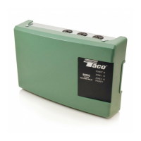
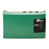
External indicator lights provide visual feedback on the switching relay's status and functionality.

Simplified Wiring

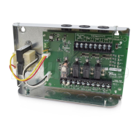
Features simplified wiring for easier and faster installation by contractors.

Sealed Relays

Utilizes sealed relays, enhancing durability and reliability in various environmental conditions.

100% Factory Tested

Each unit undergoes 100% factory testing to ensure quality and performance.

Contractor Friendly PC Board Layout

Designed with a contractor-friendly PC board layout for ease of installation and maintenance.

Universal Thermostat Compatibility

Compatible with a wide range of universal thermostats for flexible system integration.

UL Approved

Product has achieved UL approval, meeting safety standards for electrical equipment.

Extended 3 Year Warranty

Comes with an extended 3-year warranty, offering long-term protection and support.

Application Notes

120 VAC Application

Supports 1-zone switching with boiler enable or 2-zone operation without boiler enable.

240 VAC Application

Enables 1-zone switching by managing both L1 and L2 hot leads of the circulator.

Operation and Wiring

Operation Principle

Connect thermostats to R, W1, W2 terminals; relays energize to power circulators when heat is called.

Zone Control Power Input

Connect 120V AC power input to N (neutral) and H (hot) terminals for zone control.

External Diagnostics

External lights indicate status: green for power, red for heat call, showing full relay functionality.

Terminal Descriptions

Defines R, W1, W2, C, N, H, X1, X2 terminals for thermostat and power connections.

Technical Specifications

Product and Zone Details

Model SR501-HC-4 supports 1 or 2 zones.

Input Voltage and Current

Input voltage requirement is 120/60/1 VAC at 90 mA.

Enclosure Dimensions

Enclosure type is Type 1, with dimensions: Width 47/8", Height 65/8", Depth 23/8".

Relay Rating

Relay rating is 3/4 HP at 120 VAC (13.8 FLA) and 240 VAC (6.9 FLA).

Thermostat Output

The thermostat connection provides a 24 VAC Class 2 output.

Important Warnings and Guidelines

Wiring Safety and Compliance

Follow electrical codes, use copper wire. Incorrect wiring risks injury, death, or damage.

Wire Gauge Recommendations

Use 12-18 AWG for 120/240V, 14-22 AWG for thermostat, and 14-22 AWG for 24 VAC.

FCC Compliance Statement

Device complies with FCC Rules Part 15, subject to interference conditions.

Troubleshooting and Solutions

Digital Thermostat Issues

Resistor (1kΩ, 1/2W) may be needed between W and C for power-stealing thermostats.

No Heat in Zone

Check LED diagnostics. Green LED indicates power; red LED indicates heat call.

Additional Resources

Online Information Access

Scan QR code or visit website for catalog sheets, Visio stencils, and wiring guides.

Wiring Diagrams

Two Zone, No Boiler Enable Diagram

Diagram for a two-zone setup with no boiler enable functionality.

One Zone, No Boiler Enable (Same Power Source)

Diagram for one zone, no boiler enable, using the same power source.

One Zone, No Boiler Enable (Different Power Source)

Diagram for one zone, no boiler enable, using different power sources.

Product Information

Replacement Parts

Lists replacement fuse part number SR6A-001RP and optional resistor SRTR-001RP.

Warranty and Legal

Limited Warranty Statement

Details warranty terms, repair/replacement process, and exclusions for Taco products.

Warranty Limitations

States warranty is in lieu of others, excludes incidental/consequential damages.

Purchaser Rights

Warranty grants specific rights, which may vary by state regarding implied warranties.

Related product manuals