S
R 501-4
NH3 4 4 56 6
N/O N/ON/C N/CCOM COM
120 VAC
I
NPUT
TT
COM
R
W
24
VAC
TO: 120 VAC POWER
CIRCULATOR
TO: ZC
THERMOSTAT
TO: ZR
ONE ZONE
S
WITCHING RELAY
FUSE
6 AMP
POWER
ZONE 1
LED
INDICATORS
FUSE
6
AMP
NOTE 1: Resistor
(
1KΩ,
1
⁄
2
W)
may be needed
between W and C
terminals.
S
ee
N
OTE 1
TACO SR501-4 REPLACEMENT CROSS-REFERENCE
MANUFACTURER MODEL CONNECTIONS
Taco SR501-4 HN3 4 NO 4 NC 5 6 NO 6 NC R/T W/T C
Argo AR821 1 2 3 4 56 T
AR822 L1 L2 3 4 NO 4 NC 5 6 NO 6 NC R/T G/T C
Colombus MR10 L1 L2 3 4 NO 4 NC 5 6 NO 6 NC R/T G/T C
Erie SR100 L1 N3 4 NO 4 NC 5 6 NO 6 NC R/T G/T C
Honeywell RA89A 1234 T T
RA832A 1234 XX T T
R845A 1 2 3 4 56 T T
White-Rogers 889-189 1234 T T
829-845 1 2 3 4 56 T T
Features:
E
xternal Indicator Lights
Universal Replaceability
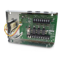
Snap-in PC Board
Simplified Wiring
Sealed Relays
Fuse Protected Outputs
100% Factory Tested
Contractor Friendly PC Board Layout
U
niversal Thermostat Compatibility
UL Approved
Extended 3 Year Warranty
Operation:
Connect a thermostat to the “T T” terminals
on the switching relay. When the thermostat
calls for heat, the relay is energized and power
is given to the circulator.
Power Input:
Connect 120 volt ac power to terminals N
and H.
Jumper Placement:
The jumper is factory installed between ter-
minals H and 3 to switch power on terminals
4 n/o and 4 n/c.
Terminal Description:
T & T Thermostat Connection
COM Common side of transformer, to power some
setback thermostats
N Neutral wire of power input
H Hot wire of power input
3 Common terminal for 4 n/o and 4 n/c
4 n/o Normally open terminal
4 n/c Normally closed terminal
6 n/c Normally closed terminal
6 n/o Normally open terminal
5 Common terminal for 6 n/o and 6 n/c
Alternative
Wiring:
ONE ZONE
SWITCHING RELAY
SR 501-4
F
USE
6 AMP
P
OWER
ZONE 1
LED
INDICATORS
F
USE
6 AMP
NH3 4 4 56 6
N
/O N/ON/C N/CCOM COM
120 VAC
INPUT
TT
COM
R
W
24
VAC
TO: 120 VAC POWER
CIRCULATOR
JUMPER
TO: TT ON
BOILER
THERMOSTAT
See
NOTE 1
Instruction Sheet
SR501-4 Switching Relay
102-375
SUPERSEDES: March 1, 2013 EFFECTIVE: December 20, 2013
Plant ID# 9300-2865
NOTE 2: When using Alternative Wiring diagram, the boiler operating
control’s ZC terminal will see the load of the circulator(s).
WARNING: When using Alternative Wiring diagram, wiring instruc-
tions must be followed so power originates from the boiler aquastat.
Failure to follow these wiring instructions may result in a secondary
source of power being connected to the boiler that may activate it
under certain circumstances, causing injury or death.
Specifications:
PRODUCT NUMBER INPUT MAXIMUM TYPE 1 ENCLOSURE
NUMBER OF ZONES VOLTAGE COMBINED LOAD WIDTH HEIGHT DEPTH
SR501-4 1 120/60/1 VAC 12 amps 4
7
/8"6
5
/8"2
3
/8"
All circulator relay connections, including ZC/ZR, are rated
1
/3 hp (6 FLA, 36 LRA) at 120 VAC.
The thermostat connection supplies a 24 VAC class 2 output.
WARNING: Wiring connections must be made in accordance with all
applicable electrical codes. Use copper wire only. 120 VAC wiring must
have a minimum temperature rating of 75°C. Failure to follow this
instruction can result in personal injury or death and/or property dam-
age. 12-18 gauge wire recommended for 120 VAC connections, 14-22
gauge wire for thermostat connections, and 14-22 gauge wire for 24
VAC source connections.
T
ypical
Wiring:
This device complies with part 15 of the FCC Rules. Operation is subject to the following two con-
ditions: (1) This device may not cause harmful interference, and (2) this device must accept any
interference received, including interference that may cause undesired operation.
Troubleshooting:
• Problem: Digital thermostats do not work correctly when connected
to a switching relay.
• Solution: Some thermostats are a “Power Stealing” type which means
they are powered by the switching relay with just 2 wires (R & W). A
resistor may be needed in order to have the thermostat work properly.
This resistor should be placed between the W & C (common) termi-
nals of the switching relay. If the thermostat manufacturer does not
supply a resistor, a 1000 ohm ½ watt resistor has proven to work with
most models and is readily available at electronic supply outlets (e.g.
Radio Shack). If the thermostat is battery powered, then check that the
batteries are fresh and installed correctly.
• Problem: No heat in a zone or room of building.
• Solution: LED diagnostic lights will help find a component that is not
working properly. The green LED should always be on, indicating that
power is connected and the solid-state fuse is good. When there is a
call for heat, the red LED will come on indicating power to the zone
circulator. This indicates the thermostat is working correctly. If the red
LED does not come on, then check the thermostat and thermostat
wiring for errors.
For information on Taco’s Switching Relays (SR)
including catalog sheet, instruction sheets, Visio
stencils and our highly praised Zone Controls
Wiring Guide, scan the QR code to the right or go to
our website: http://www.taco-hvac.com.