Reset Ratio
Once the iSeries-R is powered up, it provides outdoor reset at the supply sensor location. The iSeries-R targets
a supply temperature based on the outdoor temperature measured and the Reset Ratio dial setting. The Reset
Ratio is set using the following formula:
Maximum / Minimum System Supply Temperature (DIP switch 1 & 2)
The iSeries-R has a maximum supply function used to set a maximum supply water target tem-
perature. This function helps to protect system components, such as floor coverings, by pre-
venting excessive water temperatures. The maximum target temperature is selected using DIP
switches 1 & 2.
When selecting a maximum supply target temperature of 150°F, the iSeries-R also enables a
minimum supply target temperature of 85°F. This function is typically used in staple up radiant
floor heating applications, in order to ensure enough heat delivery during mild outdoor tempera-
tures.
If the actual supply water temperature approaches the maximum or minimum system supply, the
iSeries-R modulates the valve down and the green LED flashes rapidly (reduced output).
Minimum Boiler Return Temperature (DIP switch 3)
The iSeries-R includes a boiler protection function which prevents low temperatures back to the boiler. Whenever the
boiler sensor is installed, the iSeries-R monitors the boiler return temperature and modulates the valve down when
the return temperature is near the minimum setting. The minimum setting is selected via DIP switch 3. When the
switch is turned on, the minimum temperature is set to 120°F and when the DIP is turned off the minimum tempera-
ture is 135°F.
When using low temperature boilers such as condensing or electric, the boiler minimum temperature may be disabled by powering up
the control without a boiler return sensor. Whenever the iSeries-R is being modulated towards the closed position to protect the boiler,
the green LED flashes rapidly (reduced output).
Warm Weather Shut Down (WWSD) (DIP switch 4)
When the outdoor temperature is warmer than 70°F, the iSeries-R closes. The green LED then slowly flashes during
warm weather shut down. This function may be turned on by setting the DIP switch 4 to the on position.
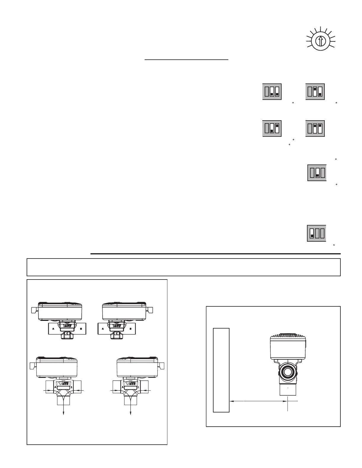
Valve Installation
1/3
1/5
1/7
1/9
2/1
2/3
2/9
3/1
3/3
Sftfu!Sbujp
2/5
2/7
Reset Ratio =
Design Supply Temperature - 72°F
72°F - Design Outdoor Temperature
PGG
PO
PGG
PO
234
PGG
PO
PGG
PO
234
234 234
Nbyjnvn;!Opof
Njojnvn;!Opof
Nbyjnvn;!261!G
Njojnvn;!96!G
Nbyjnvn;!221!G
Njojnvn;!Opof
Nbyjnvn;!241!G
Njojnvn;!Opof
3
WARNING: Actuator must be removed from the valve body before soldering. Ball valve must be in
the full open position before soldering. Valve is shipped in the full closed position.
W
A
L
L
1 1/2" Min.
Actuator
Removal
Clearance
Figure B
Figure A:
2-way
3-way
Two Position Head Placement.
Universal Body Placement.
Valve may be installed in any position, any orientation.
3-way actuator power connections must be over the supply port.
SUPPLY
RETURN
SUPPLY
RETURN
MIX
MIX
 Loading...