EasyManua.ls Logo

Taico TK10200 - User Manual

Taico TK10200
15 pages
Print Icon
To Next Page IconTo Next Page
Loading...
1
TK10200 (51.2V 200Ah)
Lithium Iron Phosphate Battery
User Manual
Question and Answer IconNeed help?

Do you have a question about the Taico TK10200 and is the answer not in the manual?

Summary

1. Notes and Warnings

1.1 Before Installation

Checks and safety steps required prior to battery installation.

1.2 Usage Guidelines

Critical operational rules and prohibitions for using the battery.

2. Introduction

3. Key Characteristics

4. Parameter Specifications

4.1 Physical Dimensions

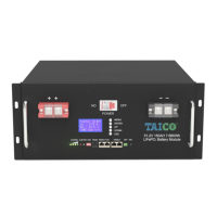
Details the physical size and weight of the battery module.

4.2 Battery Electrical Parameters

Lists critical electrical specifications like voltage, capacity, current limits, and temperature ranges.

4.3 Interface Definitions

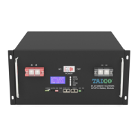
Explains the functions of the battery's interfaces, including communication ports and indicators.

5. LiFePO4 Battery Safety Operating Guidelines

5.1 Application Schematic

Provides a diagram illustrating the battery's application setup.

5.2 Tools

Lists the necessary tools for installing the batteries.

5.3 Security Equipment

Recommends essential safety equipment for handling the battery pack.

6. Installation

6.1 Installation Location

Specifies the conditions required for the battery installation location.

6.2 Installation

Describes the physical process of installing the battery module.

7. Maintenance Precautions

8. FAQ Analysis and Solutions

8.1 Undervoltage Alarm

Analyzes the cause and solution for the undervoltage alarm.

8.2 Discharge Over-current Protection

Analyzes the cause and solution for discharge over-current protection.

8.3 Temperature Protection

Analyzes the cause and solution for temperature protection issues.

8.4 Battery No Voltage Output

Analyzes the cause and solution for the battery having no voltage output.

Overview

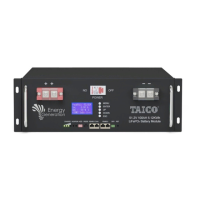
The TK10200 (51.2V 200Ah) Lithium Iron Phosphate Battery is an advanced energy storage product designed to provide reliable power for various equipment and systems. It is particularly well-suited for applications requiring high power, limited installation space, restricted bearing capacity, and a long operational lifespan.

Function Description

This battery module serves as a robust power source, incorporating a built-in Battery Management System (BMS) for comprehensive monitoring and management of battery voltage, current, and temperature. The BMS also facilitates passive equalization, balancing the charge and discharge of individual cells within the battery module to extend its cycle life. The system supports parallel expansion, allowing multiple battery packs to be connected to increase overall capacity and power, catering to diverse standby time requirements. It features an automatic dormancy function, enabling the battery to enter a low-power state when no live equipment is connected, thereby reducing self-loss.

Important Technical Specifications

Model: TK10200 (51.2V 200Ah) Nominal Voltage: 51.2V Nominal Capacity: 200Ah Combination Mode: 16 Series Dimensions (W×D×H): 482×500×280 mm Weight: Approximately 84KG Working Voltage: 43.2V – 58.4V Charging Voltage: 56.8V – 58.4V Charging Current Limiting: 10A (default, active if charging current exceeds 55A) Standard Charging Current: 20A (0.2C) Maximum Continuous Charging Current: 50A (0.5C) Standard Discharge Current: 20A (0.2C) Maximum Continuous Discharge Current: 100A (0.5C) Charging Temperature Range: 0°C – 50°C Discharge Temperature Range: -20°C – 60°C Monitoring Communications: RS232, RS485, CAN Number of Cycles: 6000 Cycles Working Environment: Humidity ≤95%; Altitude ≤4000m

Usage Features

Environmental Protection: The battery module utilizes non-toxic and pollution-free materials. Safety: The core cathode material is LiFePO4, ensuring good safety performance and a long service life. The BMS provides protection against over-discharge, over-charge, over-current, and high/low temperatures. Scalability: Flexible configuration allows for parallel expansion with multiple battery modules to meet different capacity and power demands. Low Power Consumption: The automatic dormancy function helps reduce self-loss when the battery is not actively in use. No Memory Effect: Excellent shallow charge and discharge performance. Wide Temperature Range: Operates effectively across a broad temperature range, with good discharge performance and cycle life. Portability: Its small, lightweight, and standard 19-inch embedded module design makes it easy to install and maintain.

Interface Definitions:

  • RET (Reset Key):
    • When BMS is dormant: Press for 3 seconds to activate the protection board; the "RUN" LED lights up for 0.5 seconds.
    • When BMS is active: Press for 3 seconds to put the protection board into dormancy; the lowest power lamp lights up for 0.5 seconds.
    • When BMS is activated: Press for 6 seconds to reset the protection board; all LEDs light up for 1.5 seconds. Resetting retains parameters and functions set via the upper computer. To restore initial parameters, use the "restore default value" option in the upper computer.
  • RS485-1/CAN: RJ45 interface for external communication with devices like inverters and computers.
  • RS485-2: Dual RS485 interface with a default baud rate of 9600 bps, supporting parallel battery pack communication.
  • RS232: RJ11 interface with a default baud rate of 9600 bps.
  • ADD (Address Switch): Four dial switches (1, 2, 3, 4) determine the communication address. "OFF" means 0, "ON" means 1. This allows distinguishing multiple parallel PACKs.

LED Indicators:

  • RUN: Indicates normal operation (flashing 1) or standby (according to electricity indicator).
  • ALM: Indicates an alarm (flashing 3) or protection events.
  • Electricity Indicator (L1-L4): Shows the charge/discharge status and capacity percentage. During charge, LEDs light up sequentially. During discharge, LEDs turn off sequentially.
    • 0-25%: L1 flashes 2 (charge), L1 is off (discharge).
    • 25-50%: L1 is always bright, L2 flashes 2 (charge); L1 is always bright, L2 is off (discharge).
    • 50-75%: L1-L2 are always bright, L3 flashes 2 (charge); L1-L2 are always bright, L3 is off (discharge).
    • 75-100%: L1-L3 are always bright, L4 flashes 2 (charge); L1-L3 are always bright, L4 is off (discharge).
  • Module Low Voltage: Maximum power LED flashes (flash 2), overcharge alarm ALM does not flicker.
  • Overcharge Protection: ALM flashes 3, electricity indicator shows "always bright."
  • Temperature/Overcurrent/Failure Protection: ALM flashes 3, electricity indicator shows "elimination."
  • Undercurrent Protection: ALM flashes 3, electricity indicator shows "elimination."
  • Temperature/Overcurrent/Short Circuit/Reverse Connection/Failure Protection (Discharge): ALM flashes 3, electricity indicator shows "elimination."
  • Failure (Charge/Discharge): ALM flashes 3, electricity indicator shows "elimination."

Maintenance Features

The LiFePO4 battery is largely maintenance-free, allowing for extended maintenance periods, typically every three months. Routine Checks:

  • Inspect pole columns and connection lines for looseness, damage, deformation, or corrosion.
  • Check the battery case for damage or deformation.
  • Observe the running indicator light: green for normal operation. If only the last CAPCITY light flickers, it indicates low battery power, signaling an impending output cutoff.
  • Troubleshooting Alarms: If the ALM red light flashes and an alarm sounds, check for correct battery connection or over-current. Press the RST reset key to see if the fault clears after restart. If not, contact the manufacturer. Do not open the battery case.
  • Parallel Battery Replacement: In multi-battery parallel applications, if a battery needs replacement, ensure the voltage difference between the new battery and existing ones is within 2V. A large voltage difference can lead to high current charging of the low-voltage pack or over-current protection, preventing proper charging.
  • Record Keeping: Document power outage times and durations, and track battery power supply times for detailed statistics.

FAQ Analysis and Solutions:

  • Undervoltage Alarm: ALM flickers, RUN off.
    • Cause: Load current exceeds discharge protection, or battery protection panel failure.
    • Solution: The protection board locks until the charger activates at the charging input.
  • Discharge Over-current Protection: ALM flickers, RUN off.
    • Cause: Load current exceeds discharge protection, or battery protection panel failure.
    • Solution: The protection board locks until the charger activates at the charging input.
  • Temperature Protection: ALM flickers, RUN off.
    • Cause: Ambient temperature too high or too low.
    • Solution: Protection board recovers and ALM turns off when NTC temperature returns to normal.
  • Battery No Voltage Output: Power indicator off, battery voltage 0V.
    • Cause: Battery not activated, or BMS abnormal.
    • Solution: Activate or reset the battery via the RST key. If no voltage output persists, contact the manufacturer.

Taico TK10200 Specifications

General IconGeneral
BrandTaico
ModelTK10200
CategoryCamera Accessories
LanguageEnglish

Related product manuals