Do you have a question about the Taig Tools Micro Lathe II and is the answer not in the manual?
Details physical dimensions and capabilities of the lathe, including swing, length, and tool bit size.
Provides specifications for the lathe spindle, such as bearing type, nose size, and collet diameter.
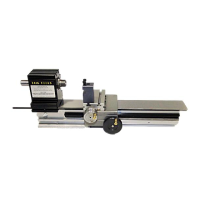
Identifies major parts of the lathe through an illustrated diagram with labels.
Lists essential safety guidelines for lathe operation, emphasizing eye protection and secure chucking.
Reinforces critical safety protocols for operation, including handling the pulley and tool bit.
Details lathe cleaning, oiling procedures, and corrosion prevention for extended service life.
Lists approximate spindle speeds based on motor pulley to lathe pulley combinations.
Explains how to position the motor for proper belt contact and tension adjustment.
Describes how to rotate the eccentric to engage gears on the rack for operation.
Provides approximate cutting speeds in RPM for different materials and workpiece diameters.
Advises on using cutting fluids, carbide tool bits, and proper sharpening techniques.
Explains how to set tool bits on center and use the steady rest for workpiece support.
Describes the depth stop used to provide a stop for workpieces held in the chuck.
Explains the four-jaw chuck, its independent jaws, and versatility for various shapes.
Illustrates the lathe configured with a four-jaw chuck for workpiece mounting.
Illustrates the lathe configured with a three-jaw chuck for workpiece mounting.
Describes face plates used for running shafts between centers and fixturing special jobs.
Describes 1x1 inch square angle brackets, including hardware for mounting.
Shows how faceplates and angle brackets are utilized in lathe operations.
Illustrates the steady rest for supporting long workpieces during machining.
Explains the use of collets for small diameter shafts and holding cutters, and the closer nut.
Describes blank collets for making special sizes or modifying standard screws.
Illustrates the full circle jaw for holding thin disks, clock gears, or thin wall tubes.
Shows collets, depth stop, and related components in a practical context.
Describes the 3 1/4 inch all-steel scroll chuck with aluminum top (soft) jaws.
Explains the process of truing soft jaws on the spindle chuck for best accuracy.
Details machining soft jaws with steps and highlights their advantages for workpieces.
Provides a tip for maintaining workpiece position by marking jaws and workpiece.
Explains how to bore jaws and cut steps for holding thin disks or clock gears.
Describes using machined jaws to hold thin wall tubes without damage.
Explains its use for angles, short tapers, and controlling cut length.
Describes how the compound attaches to the crosslide and can be clamped at any angle.
Explains the die holder's purpose for aligning button-dies to cut true, untapered threads.
Advises on preparing the workpiece end with a chamfer before screwing in the button die.
Details the milling attachment's vertical travel and crosslide dial for precise movement.
Provides approximate cutting speeds in RPM for end mills on various materials.
Discusses using carbide tipped router bits for cutting aluminum, brass, plastics, and wood.
| Brand | Taig Tools |
|---|---|
| Model | Micro Lathe II |
| Category | Tools |
| Language | English |