EasyManua.ls Logo

Tait Orca 5040 - User Manual

Tait Orca 5040
20 pages
Print Icon
To Next Page IconTo Next Page
Loading...
D
PART
Servicing the radio
This part describes the disassembly and reassembly of Tait Orca
5000 handportables and the servicing of some key mechanical
and ancillary devices.
Information is also provided on ordering spare parts for servicing
handportables.
Contents
Servicing the radio
Servicing the radioServicing the radio
Servicing the radio
.........................................................................................
..................................................................................................................................................................................
.........................................................................................D-3
D-3D-3
D-3
Screw head types ...................................................................................................D-3
Disassembling the radio
Disassembling the radioDisassembling the radio
Disassembling the radio
................................................................................
................................................................................................................................................................
................................................................................D-4
D-4D-4
D-4
Removing the front panel from the chassis ........................................................... D-4
Removing the shield from the chassis ................................................................... D-5
Removing the PCB from the chassis ...................................................................... D-6
Removing the rear panel ....................................................................................... D-7
Replacing key mechanical and ancillary devices
Replacing key mechanical and ancillary devicesReplacing key mechanical and ancillary devices
Replacing key mechanical and ancillary devices
............................................
........................................................................................
............................................D-8
D-8D-8
D-8
Replacing the lens (Orca 5020, Orca 5035 and Orca 5040) ...................................D-8
Replacing the PTT keypad ..................................................................................... D-8
Replacing the speaker ............................................................................................ D-9
Replacing the LCD display (Orca 5020, Orca 5035 and Orca 5040) ...................... D-9
Replacing the shield, user interface PCB assembly and polyester dome
(Orca 5020, Orca 5035 and Orca 5040) ............................................................... D-12
Replacing the antenna connector, channel selector switch and volume control switch........ D-12
Replacing the microphone .................................................................................. D-12
Replacing the battery and speaker contacts ........................................................ D-12
Replacing the tact switch ..................................................................................... D-12
Reassembling the radio
Reassembling the radioReassembling the radio
Reassembling the radio
................................................................................
................................................................................................................................................................
................................................................................D-13
D-13D-13
D-13
Rear panel reassembly and replacing the auxiliary flexible PCB ......................... D-13
Fitting the PCB to the chassis and replacing the RF out assembly ....................... D-14

Other manuals for Tait Orca 5040

Question and Answer IconNeed help?

Do you have a question about the Tait Orca 5040 and is the answer not in the manual?

Summary

PART D Servicing the radio

Servicing the Radio Overview

General overview of radio servicing limitations and components.

Screw Head Types

Details on Torx head screws and driver usage for radio disassembly.

Disassembling the Radio

Step-by-step guide to taking apart the Tait Orca 5000 radio.

Removing the Front Panel

Procedure for detaching the front panel from the radio chassis.

Removing the Shield Sub-assembly

Instructions for removing the shield and associated components.

Removing the PCB

Steps to detach the Printed Circuit Board from the radio chassis.

Removing the Rear Panel

Guide to disassembling and removing the rear panel of the radio.

Replacing Key Mechanical and Ancillary Devices

Procedures for replacing essential radio components.

Replacing the Lens

Instructions for replacing the lens on specific Orca models.

Replacing the PTT Keypad

Guide to replacing the Push-To-Talk keypad assembly.

Replacing the Speaker

Steps for removing and installing the radio speaker.

Replacing the LCD Display

Procedure for replacing the LCD screen on specific Orca models.

Replacing Shield, UI PCB, and Polyester Dome

Replacing integrated user interface components on specific models.

Replacing Antenna Connector, Channel;Volume Switches

Procedure for replacing antenna connector and control switches.

Replacing the Microphone

Instructions for removing and installing the radio microphone.

Replacing Battery and Speaker Contacts

Steps to replace electrical contacts for battery and speaker.

Replacing the Tact Switch

Guide to replacing the tactile switch on the PCB.

Reassembling the Radio

Instructions for putting the Tait Orca 5000 radio back together.

Rear Panel Reassembly and Auxiliary PCB

Procedure for reassembling the rear panel and flexible PCB.

Fitting the PCB and RF Out Assembly

Steps to install the PCB and RF output assembly.

Fitting the Front Panel

Procedure for attaching the front panel to the chassis.

Spares Kits Information

Details on available spare parts kits for servicing the radio.

Overview

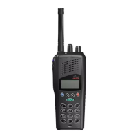
The Tait Orca 5000 handportable radio is a robust communication device designed for reliable performance in various operational environments. This manual provides comprehensive instructions for the servicing, maintenance, and reassembly of the radio, focusing on key mechanical and ancillary components. The manufacturing process for the Orca 5000 does not allow for direct servicing access to individual components on the main PCB, meaning that service repairs are limited to specific mechanical and ancillary devices that are associated with the main PCB. This approach ensures that complex internal circuitry remains intact while allowing for the replacement of commonly worn or damaged external and interface parts.

Function Description

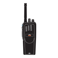
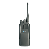
The Tait Orca 5000 handportable radio serves as a portable two-way communication device, enabling users to transmit and receive radio signals. Its primary function is to facilitate clear and dependable voice communication in professional settings. The radio incorporates essential controls for channel selection, volume adjustment, and push-to-talk (PTT) functionality, all designed for intuitive operation. The device is built to withstand the rigors of daily use, with a design that prioritizes durability and ease of handling.

Usage Features

The Orca 5000 handportable radio features a user-friendly design with several key components that contribute to its operational effectiveness:

  • Front Panel Assembly: This integral part houses the display, keypad, and speaker, providing the primary interface for user interaction.
  • Lens: For models Orca 5020, Orca 5035, and Orca 5040, a protective lens covers the display, safeguarding it from scratches and impacts while maintaining visibility.
  • PTT Keypad: The Push-To-Talk keypad includes the main PTT key and additional function keys, allowing for quick and efficient communication and access to various radio features.
  • Speaker: An integrated speaker ensures clear audio output for incoming transmissions, crucial for effective communication in noisy environments.
  • Keypad (Orca 5020, Orca 5035, Orca 5040): These models feature a dedicated keypad for inputting information or accessing menu options, enhancing the radio's versatility.
  • LCD Display (Orca 5020, Orca 5035, Orca 5040): A Liquid Crystal Display provides visual feedback, showing channel information, battery status, and other relevant operational data.
  • Shield with User Interface PCB Assembly and Polyester Dome (Orca 5020, Orca 5035, Orca 5040): This assembly protects the internal electronics and provides a robust housing for the user interface components, contributing to the radio's overall durability.
  • Main PCB Assembly: The central circuit board that contains the core electronic components of the radio, responsible for processing radio signals and managing device functions.
  • Antenna Connector: A standard connector for attaching an external antenna, which is essential for transmitting and receiving radio signals effectively.
  • Channel Selector Switch: Allows users to easily switch between different communication channels, providing flexibility in multi-channel environments.
  • Volume Control Switch: Enables users to adjust the audio output level of the speaker to suit their listening preferences and ambient noise conditions.
  • Microphone: An integrated microphone captures the user's voice for transmission, ensuring clear outgoing audio.
  • Speaker Contacts: Electrical contacts that connect the speaker to the main PCB, ensuring proper audio functionality.
  • Battery Contacts: Contacts that facilitate the connection between the radio and its battery pack, providing power to the device.
  • PTT Tact Switch: The underlying switch mechanism for the PTT button, ensuring a responsive and reliable push-to-talk function.
  • RF Out Assembly: Components related to the radio frequency output, crucial for transmitting signals.
  • Auxiliary Flexible PCB: A flexible printed circuit board that connects various components, allowing for compact and efficient internal design.

Maintenance Features

The Tait Orca 5000 is designed for maintainability, with specific procedures outlined for replacing key components. Most screws in the handportables are Torx head screws, and a Torx T6 driver bit is provided in the service kit to ensure proper removal and replacement. When replacing screws, it is important to use the correct driver and apply the specified torque (2 inch pounds for Torx head 1.8x5 mm screws) to prevent damage.

Disassembly Procedures:

  • Removing the Front Panel from the Chassis: This involves unscrewing the antenna, detaching the battery pack, and carefully removing the channel selector and on/off/volume control knobs. Side cutters are used to gently prise off the knobs, taking care not to damage the knob label or switch shaft. Chassis screws at the base of the radio are removed, and the battery is used as leverage to separate the front panel from the chassis.
  • Removing the Shield Sub-assembly from the Chassis: The radio's internal assembly is placed shield-side up, and pressure is applied to the shield sub-assembly above the slot clip detail. A flat-bladed screwdriver is then inserted into the gap between the shield and chassis and twisted to release the shield.
  • Removing the PCB from the Chassis: The knob seal is removed, followed by the screw through the PA shield. Three nuts for the antenna connector and knobs are removed using an 8 mm long reach socket driver, along with their ribbed lock washers. The PCB is then gently lifted and pulled away from the chassis.
  • Removing the Rear Panel: After disassembling the radio to the PCB level, a small flat-bladed screwdriver is used to push the auxiliary dummy rear cover lugs free. The rear panel can then be slid forward or twisted off. The rear panel seal and the RF contact pin must be carefully removed and retained. The auxiliary flexible PCB, along with its seal, is lifted from the lower lefthand corner using a calibration pin and removed as a unit.

Replacement Procedures for Key Mechanical and Ancillary Devices:

  • Replacing the Lens (Orca 5020, Orca 5035, Orca 5040): The radio must be disassembled, and the old lens carefully prised away. Any remaining adhesive is cleaned, and the new lens is applied by peeling off the backing, pressing firmly into position, and then removing the clear plastic film from the front.
  • Replacing the PTT Keypad: After removing the front panel, the PTT retaining plate is released by gently pushing the central latch from the inside of the front panel. Care must be taken not to lose the two pins that act as actuators for the function keys. The new retaining plate is inserted by fitting the bottom tab into the corresponding hole and bending it slightly to slot the top tab into place.
  • Replacing the Speaker: The front panel is removed, and the old speaker is carefully removed using a scalpel and a flat screwdriver. Any remaining adhesive is cleaned with alcohol, and a new adhesive ring and speaker are secured, ensuring proper tab alignment.
  • Replacing the LCD Display (Orca 5020, Orca 5035, Orca 5040): The shield is removed from the front panel, and the user interface loom is unplugged from the main PCB. The LCD display loom is unplugged from the user interface PCB, and the old display is removed. The new LCD display is positioned on the shield, its loom passed through the gap, and plugged into the user interface PCB, securing the connector lugs. The user interface PCB loom is then plugged into the main PCB and secured. The shield and front panel are then refitted.
  • Replacing the Shield, User Interface PCB Assembly, and Polyester Dome (Orca 5020, Orca 5035, Orca 5040): These components are replaced as a complete assembly. The old shield is removed from the front panel, and the user interface loom is unplugged. The LCD display assembly is transferred from the old shield to the new one. The user interface loom is plugged into the new user interface PCB, and the shield is reassembled onto the chassis.
  • Replacing the Antenna Connector, Channel Selector Switch, and Volume Control Switch: The radio is disassembled to the PCB level, and the PCB is removed. A vacuum-operated solder station is used to remove the old components, and new ones are soldered in place during reassembly.
  • Replacing the Microphone: The radio is disassembled to the PCB level, and the PCB is removed. A desoldering station is used to remove the old microphone. The new microphone is aligned with the marks on the PCB (as it is polarised) and soldered in place using a light-tip soldering iron, ensuring it does not hang over the edge of the PCB.
  • Replacing the Battery and Speaker Contacts: The radio is disassembled to the PCB level, and the PCB is removed. When replacing one contact, both should be replaced. A heavy-tip soldering iron is used, applying solder to the PCB rather than directly to the heat-sensitive contacts, which should not be heated above 260°C. Pliers can be used to hold the contact in place.
  • Replacing the Tact Switch: The radio is disassembled to the PCB level, and the PCB is removed. A desoldering station or solderwick is used to remove the old PTT tact switch, ensuring all solder is removed from both sides of the board. The new PTT tact switch is placed on the board and soldered in place using a heavy-tip soldering iron.

Reassembly Procedures:

  • Rear Panel Reassembly and Replacing the Auxiliary Flexible PCB: The flexible PCB with its seal is firmly pushed into the chassis, aligning the notch with the locating pin. The rubber must sit flush with the chassis to ensure proper fit of the rear panel and battery. The flexible PCB is folded over, and the contact area is fitted snugly onto the chassis. The rear panel seal is replaced by tucking its tags under the chassis lip and folding it over the flexible PCB, ensuring the RF contact pin is correctly positioned and the seal is flush. The rear panel is slid on from the top and forced into place by pressing the top edge against a table until it clips home, minimizing any gap. The auxiliary dummy cover is refitted by pushing its lugs into the holes, and the chassis plug seal is pushed onto the chassis boss.
  • Fitting the PCB to the Chassis and Replacing the RF Out Assembly: The battery contact seal is placed over the battery contacts (not into the chassis) to prevent squashing. The replacement RF out assembly is fitted. If removed, the antenna connector and switches are fitted onto the PCB (but not soldered yet), aligning them with the chassis holes. As the PCB is lowered, the accessory flex protruding from the chassis must fit into the PCB socket. The PCB is fully seated, and the PA screw is loosely fitted. The switches are centered, and the washers are replaced with the cone facing up. The black nuts for the two switches are replaced and tightened to 10 inch pounds using an 8 mm long reach socket driver. The PA screw is tightened to 2 inch pounds. Finally, the antenna connector and switches are soldered in place using a heavy-tip soldering iron, taking care not to damage surrounding components. The knob seal is replaced over the antenna connector and switches.
  • Fitting the Shield to the Chassis: The microphone grommet is replaced over the microphone. The shield is replaced from the top, ensuring the two chassis pins enter the two shield holes. If the main seal needs replacing, the new seal is placed so its notch matches the chassis notch (behind the channel selector switch) and its profile matches the chassis. A finger is run around the seal to ensure it fits properly into its retaining well.
  • Fitting the Front Panel to the Chassis: The radio is placed into the front panel top-first, inserting the antenna connector and knob switches through their holes. The radio is gently eased into the front panel until the chassis edge is flush with the front panel edge, ensuring the seal is not pinched. The battery can be used as leverage if needed. The two chassis screws at the base of the radio are replaced and tightened to 2 inch pounds. Finally, new knobs are placed on the radio after applying a spot of Loctite™ 680 to each switch shaft. The top of each knob is firmly pressed against a firm surface (without damaging it) to ensure no gap between the knob base and the knob label.

These detailed instructions ensure that the Tait Orca 5000 handportable radio can be effectively maintained and repaired, extending its operational life and ensuring continued reliable communication.

Tait Orca 5040 Specifications

General IconGeneral
BrandTait
ModelOrca 5040
CategoryPortable Radio
LanguageEnglish

Related product manuals