D - 10 Replacing key mechanical and ancillary devices
09/01 IPN: M5000-00-102
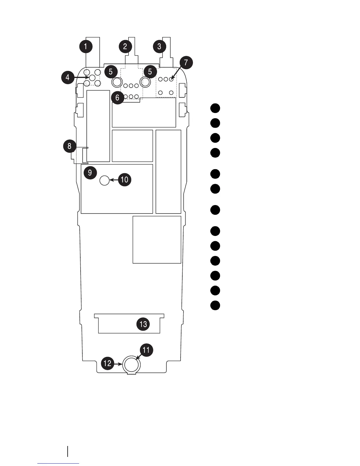
Figure D-8: Bottom surface of the PCB, which is visible when the shield has been removed from the chassis
antenna connector
channel selector switch
on/off/volume control switch
antenna connector pin placement
(5 pins)
speaker contact pin placement
channel selector pin placement
(6 pins)
on/off/volume control pin
placement (5 pins)
PTT tact switch
PA can
PA screw
microphone placement
microphone grommet placement
user interface loom connector
1
2
3
4
5
6
7
8
9
10
11
12
13
 Loading...