20 Connection TB8100 Installation Guide
© Tait Electronics Limited February 2007
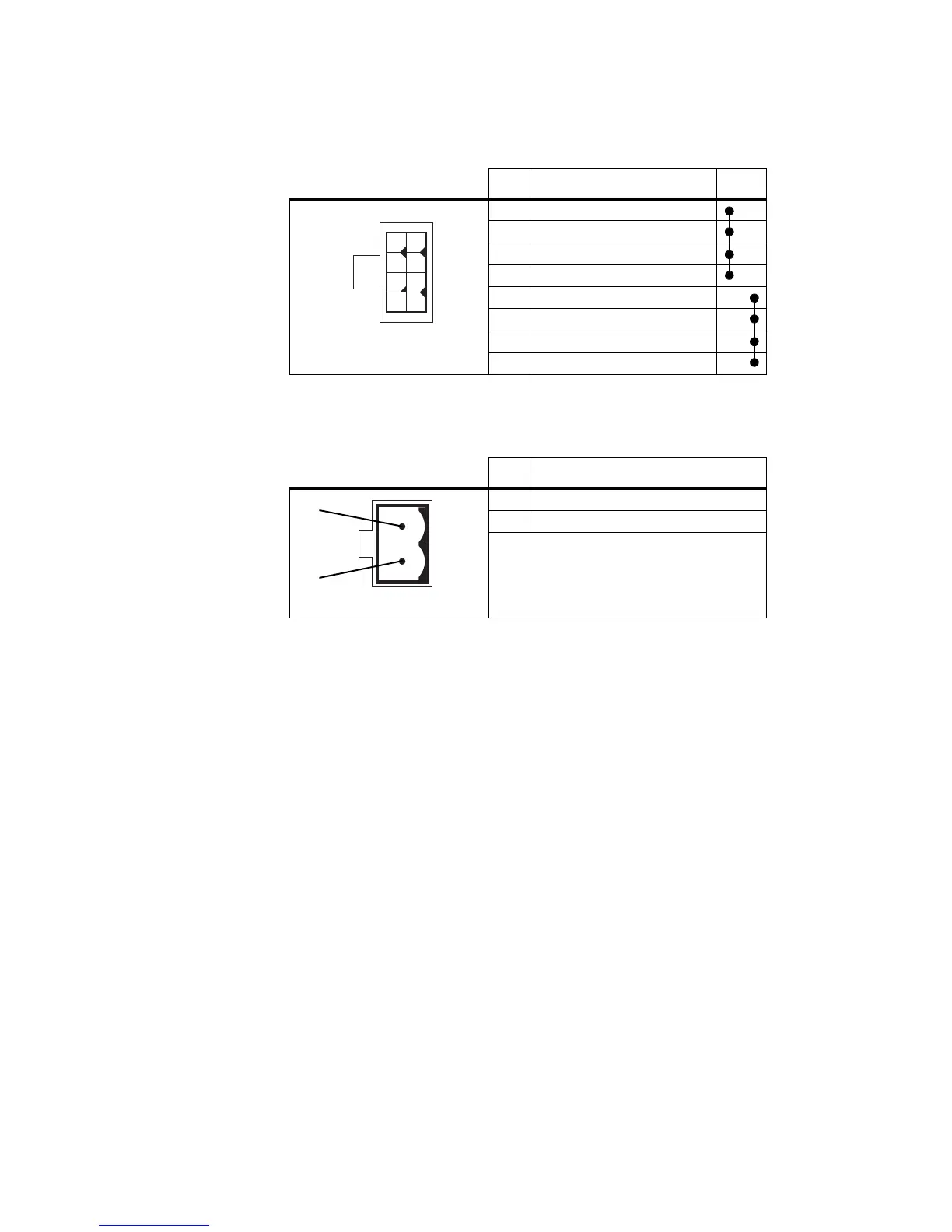
manufactured before August 2004 are given in the following table. Note
that pins 1 to 4 and pins 5 to 8 on this connector are linked.
The pin allocations for the 2-way connector fitted to PMUs manufactured
from August 2004 onwards are given in the following table.
Reciter Auxiliary DC
Input from PMU
The system interface board in the reciter has an auxiliary DC input
connector. DC from the auxiliary DC output on the PMU can be supplied
to the +AUX_V pin on the system interface connector via this input (see
“PMU Auxiliary DC Output” on page 19).
The pin allocations for the auxiliary DC input on the system interface board
are given in the following table. Older boards use the 4-way connector,
while the TaitNet RS-232 board and all other boards manufactured after
March 2005 use the 2-way connector. Note that pins 1 & 3 and pins 2 & 4
on the 4-way connector are linked. Refer to “System Connections” on
page 22 for the pin allocations for +AUX_V on each system interface board.
Pin Description Links
1 +V output
2 +V output
3 +V output
4 +V output
5 ground
6 ground
7 ground
8 ground
Pin Description
1 +V output
2 ground
1
5
26
37
48
8-way connector - external view
2-way connector - external view
b
c

 Loading...


