TB8100 Installation Guide Connection 23
© Tait Electronics Limited February 2007
Isolated E&M This system interface board is fitted to reciters bearing the product code
TBA4xxx-0C0x or TBA5xxx-0C0x. If purchased separately, it has the
spares code TBA-SP-S0C0. It provides the following:
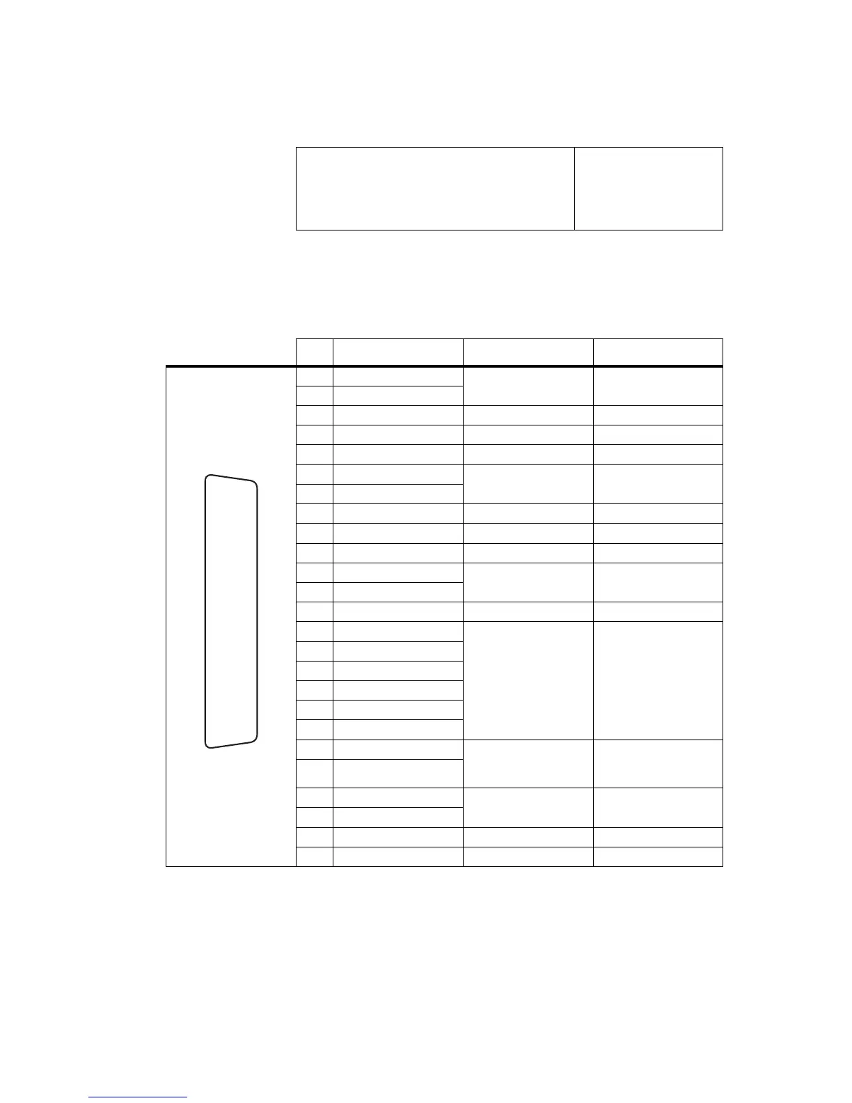
It is fitted with a 25-way female D-range connector and a 4-way auxiliary
DC input connector. The pin allocations for the D-range are listed in the
table below, and the pin allocations for the DC input connector are provided
in “Reciter Auxiliary DC Input from PMU” on page 20.
■ transformer isolated 600Ω balanced audio I/O
■ opto-isolated keying
■ opto-isolated gate output
■ digital I/O (2 outputs, 2 inputs, 4 bi-directional)
■ Tx key
■ Tx relay
■ Rx gate
■ RSSI
Pin Signal Name Signal Type Notes
1 Rx line out +
audio output transformer isolated line
2 Rx line out –
3 Rx audio out audio output
4 audio ground ground
5 Tx audio in audio input
6Tx line in +
audio input transformer isolated line
7Tx line in –
8 RSSI DC signal
9 Rx gate output open collector
10 Tx key input active low
11 digital out 1
a
output open collector
12 digital out 2
13 +AUX_V power output from auxiliary DC input
14 digital in 1
input
5V TTL logic
active low
15 digital in 2
16 digital in/out 3
b
17 digital in/out 4
b
18 digital in/out 5
b
19 digital in/out 6
b
20 opto +/–
isolated keying input
input voltage range
±10VDC to ±60VDC;
current rating 10mA
21 opto –/+
22 relay +/–
isolated gate output
23 relay –/+
24 Tx relay output open collector
25 ground ground
a. If a base station with a 12V PA is configured for Deep Sleep, digital out 1 is dedicated to Power Saving control and
cannot be used for any other Task Manager function.
b. On version 1 and later system interface boards, digital inputs 3, 4, 5, and 6 may also be configured as outputs using
a Task Manager statement. For more details refer to “Digital Interface” on page 124 of the Installation and Oper-
ation Manual, and to the Service Kit documentation.
external view
B
C
D
E
F
G
H
I
J
1)
1!
1@
1#
1$
1%
1^
1&
1*
1(
2)
2!
2@
2#
2$
2%

 Loading...


