50 TM8000 Encryption Midian Encryption Programming and Service Manual
June 2006 © Tait Electronics Limited
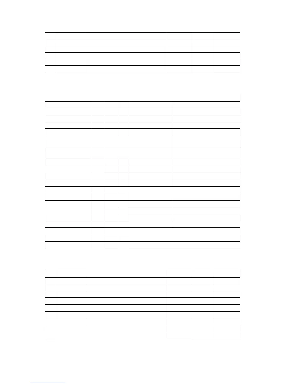
Signal levels and pin assignments
External Connector (SK1) 15way D Range Socket
13 IOP_GPI05 Programmable Port, CS 2 Digital 3.3 V CMOS
14 IOP_GPI06 Programmable Port, CS 3/wakeup/indicator Digital 3.3 V CMOS
15 IOP_GPI07 Programmable Port, CS 4/wakeup/indicator Digital 3.3 V CMOS
16 DGND Digital ground Ground
17 IOP_RXD Asynchronous serial port - receive data Digital 3.3 V CMOS
18 IOP_TXD Asynchronous serial port - Transmit data Digital 3.3 V CMOS
Function Mode Name Pin Module TM8000 Radio
Power Supply V+ 1 5V regulated
Reset I/P RS 2 Active low Resets when supply below 4.75V
Tx pressel I/P PTT 3 Active low CMOS
Busy I/P RX 4 Active low CMOS
Mode I/P MO 5 Active low Momentary or level sensitive
Data to Scrambler I/P D-SC 6
Hardwired module
programming I/P
If required
Data to Radio O/P D-RA 7
Hardwired module
programming O/P
If required
Mode Indicator O/P IND 8 Active high 3mA into LED
Emergency I/P EMG 9 Active Low Module pull-up to 5V
Code select 8 I/P CS8 10 Active Low Module pull-up to 5V
Code select 4 I/P CS4 11 Active Low Module pull-up to 5V
Code select 2 I/P CS2 12 Active Low Module pull-up to 5V
Code select 1 I/P CS1 13 Active Low Module pull-up to 5V
Ground Gnd 14
Transmitter to scrambler I/P TX-SC 15 AC coupled to 250Hz 200 mV p-p at 1kHz for 2/3 max dev
Scrambler to transmitter O/P SC-TX 16 DC coupled Approx. unity thru gain
Receiver to scrambler I/P RX-SC 17 AC coupled to 250Hz 650 mV p-p at 1kHz for 2/3 max dev
Scrambler to receiver O/P SC-RX 18 DC coupled Approx. unity thru gain
Audio alert O/P AL 19 DC Coupled
Trunking delay I/P TRK 20 Provision for future
Pin Signal Description Signal Type Levels Conditions
1 RX_MUTE Comparator OP amp output from RSSI line Digital 0 - 5 V
2 AUX_MIC_IN Auxiliary microphone input (electret bias) Analogue 7.5 mV 3.0 V Bias
3 RX_AUD Receive audio output post Vol, AC coupled Analogue 1.0 Vp-p 100 ohms
4 +5V + 5 Volts regulated DC 5V
5 RSSI / Ext PTT Analogue RSSI output / optional PTT input Analogue .5-2.5 Vdc 1000 ohms
6 D_RA Programe out (Data to Radio) Digital 5 V
7 D_SC Programe in (Data to Scrambler) Digital 5 V
8 IND Module indicator output Digital Active high 3mA out
9 IOP_RXD Asynchronous serial port - receive data Digital 3.3 V CMOS