This document is a workshop manual for the Takeuchi TB23R Compact Excavator, identified by BOOK No. CD5E000 and Serial No. 12300007~. It provides comprehensive information for maintenance operations, including disassembly and reassembly procedures, checks, maintenance reference values, troubleshooting, and outline specifications. The manual emphasizes safety and proper handling of the machine and its components.
The manual begins with a foreword outlining its purpose: to assist personnel in maintenance, disassembly, reassembly, checks, and troubleshooting. It clarifies that the information is subject to change due to design modifications. For orientation, the front of the machine is defined as the end with the dozer blade, and the rear is the end with the travel motors. Right and left sides are determined from the operator's perspective when seated. Users are instructed to include the machine's serial number (stamped on the identification plate) in all reports, inquiries, and parts orders. The manual also specifies that it is a controlled document, and updates will be provided to the person in charge.
Symbols are used throughout the manual to convey specific instructions:
- A square with an arrow indicates a cross-reference to another section.
- A wrench symbol indicates a tightening torque requirement.
- A triangle with a weight symbol indicates the mass of a part or device.
Safety is paramount, with a dedicated section on "Safety Precautions." The safety alert symbol (an exclamation mark within a triangle) signifies important safety information. Signal words—"DANGER," "WARNING," and "CAUTION"—are used to indicate the severity of potential hazards:
- DANGER: Imminently hazardous situation, resulting in serious injury or death if not avoided.
- WARNING: Potentially hazardous situation, resulting in serious injury or death if not avoided.
- CAUTION: Potentially hazardous situation, resulting in minor or moderate injury if not avoided.
- IMPORTANT: Used for situations that can result in machine or component damage.
The manual stresses that it is intended for trained and qualified personnel only, and adequate safety precautions must be taken. Key safety rules include:
- Operation, inspection, and maintenance by trained and qualified personnel only.
- Understanding and following all rules, regulations, precautions, and safety procedures.
- Avoiding work under the influence of alcohol, drugs, medication, fatigue, or insufficient sleep.
- Wearing appropriate clothing and personal protective equipment (hard hat, safety shoes, glasses, filter mask, gloves, ear protection). Loose clothing or accessories that can catch on controls or moving parts are prohibited. Oily or fuel-stained clothing is also a fire hazard.
- Using anti-explosive electrical fixtures and lights when inspecting fuel, oil, coolant, or battery fluid to prevent ignition.
- Attaching a "DO NOT OPERATE" tag to the starter switch or control lever after stopping the engine and removing the key to prevent unauthorized starts during maintenance.
- Preventing unauthorized personnel from entering the work area to avoid injury from flying debris during grinding, welding, or hammering.
- Using correct, undamaged tools suited for the operation.
- Periodically replacing important safety parts like fuel hoses and any parts showing irregularities.
- Providing and knowing how to use a fire extinguisher and first aid kit.
- Preparing the work area by selecting a firm, level, well-lit, and ventilated space, clearing obstacles, and eliminating slippery areas.
- Exercising caution when tilting up the platform: lower working equipment, stop the engine, and support the platform firmly with a stopper.
- Cleaning the machine before maintenance, covering electrical parts during washing, and avoiding water/steam on the battery, sensors, connectors, or operator's seat area.
- Stopping the engine before performing maintenance; if the engine must run, work as a two-person team.
- Staying clear of moving parts, including the rotating fan and fan belts.
- Securely blocking the machine or any component that may fall, especially when working underneath or on hydraulic cylinders.
- Securely blocking working equipment when repairing or replacing cutting edges or bucket teeth.
- Securing the engine hood or cover when opened, and avoiding opening them on slopes or in strong winds.
- Placing heavy objects in a stable position, particularly when removing or installing the hoe attachment.
- Observing cautions when working on the machine, such as keeping the foot area clean, not spilling oil/grease, not leaving tools around, watching steps, and using steps/handrails for climbing.
- Exercising extreme caution when fueling: no smoking or open flames, no refueling with the engine running or hot, no fuel spills on hot components, maintaining control of the nozzle, not overfilling the tank, cleaning up spills immediately, securely tightening the fuel cap, using the correct fuel grade, and never using fuel for cleaning.
- Being careful with hot and pressurized components: stop the engine and allow the machine to cool before inspection/maintenance, as the engine, muffler, radiator, hydraulic lines, and other parts can cause burns. Engine coolant, oil, and hydraulic fluid are hot and under high pressure; loosen caps and plugs slowly to avoid spurting.
- Handling hoses carefully: fuel, oil, or hydraulic fluid leaks can cause fires; do not twist, bend, or hit hoses; replace twisted, bent, or cracked hoses; retighten loose connections.
- Being careful with hot cooling systems: do not remove the radiator cap or drain plugs when the coolant is hot; stop the engine, let it cool, then loosen slowly.
- Exercising extreme caution with fluids under pressure: release all pressure before working on the hydraulic system. Hydraulic fluid under pressure can penetrate skin or eyes, causing injury or blindness. Wear safety goggles and heavy gloves, and use cardboard or wood to search for leaks. Seek immediate medical attention if fluid is injected into the skin.
- Being careful with grease under pressure, especially with the track adjuster. Loosen the grease discharge valve slowly, no more than one full turn, and keep body parts away from the valve.
- Releasing all pressure before working on the hydraulic system: gradually loosen the vent plug, move control levers/pedals, and loosen plugs/screws/hoses slowly.
- Handling the accumulator with care due to high-pressure nitrogen gas: do not disassemble, bring near fire, make holes, weld, fuse, or subject to shock. Release gas properly before disposal by contacting a Takeuchi service agent.
- Disconnecting the battery before working on the electrical system or welding: remove the negative (-) cable first, and connect it last.
- Checking after maintenance: gradually raise engine speed, check for leaks, and verify proper machine operation.
- Disposing of wastes properly: funnel fluids into containers and follow regulations for oil, fuel, coolant, refrigerant, solvents, filters, batteries, and other harmful substances.
- Having Takeuchi service agents repair welding cracks or other damage, or ensuring qualified personnel perform the work.
- Keeping all safety signs clean, legible, and replacing damaged ones.
Cautions During Disassembly and Assembly:
- Clean the machine before disassembly.
- Record machine conditions before disassembly (model, serial number, hourmeter, reason for repairs, filter dirtiness, fuel/oil conditions, part damage).
- Mark parts for easy reassembly.
- Clean and arrange all disassembled and new parts.
- Replace all seals and cotter pins with new ones.
- Keep parts that should not contact oil/water (electrical parts, rubber, V-belts) separate from oily parts.
- Use a press for installing bearings, bushings, and oil seals to avoid damage.
- Clean all joining surfaces.
- Wrap seal tape from the front end, tightly, leaving 1 or 2 threads bare, overlapping by about 10 mm.
- Fit snap rings with the bigger, rounder side facing mating surfaces.
Cautions During Removal and Installation of Hydraulic Units:
- Ensure hydraulic oil temperature has dropped.
- Bleed residual pressure from piping and the hydraulic oil tank.
- Install caps or plugs on all openings to prevent dirt ingress.
- Wipe the unit thoroughly to distinguish hydraulic oil from potential leaks.
- Prevent damage to the plating on the hydraulic cylinder rod.
- Remove and install hydraulic cylinders with the rod fully retracted.
- Bleed air after replacing hydraulic oil or devices.
- Pressurize the hydraulic tank after installation to prevent pump cavitation and extend pump life.
Cautions During Removal and Installation of Piping:
- For hydraulic hoses, tighten to torque, loosen slightly, then retighten. Tighten fittings until surfaces fit snugly. Seal-taped pieces are excluded.
- Use two spanners on opposite sides to prevent twisting hoses or steel pipes.
- After installation, apply maximum working pressure 5-6 times and check for leaks.
Handling of Seals:
- Clean O-ring grooves and remove burrs.
- Do not twist O-rings; remove twists with fingertips.
- Be careful not to damage seals during insertion.
- For floating seals: wipe oil off O-ring and housing, apply thin gear oil to contact surfaces, and turn the seal 2-3 times after assembly for snug fit.
- Apply grease to the lip of the oil seal to prevent wear during initial startup.
Tightening Torques:
The manual provides detailed tightening torque specifications for various components:
Hydraulic Hoses:
| Hose Fitting Size |
Union Nut (G) N·m (ft-lb) |
Taper Thread (R) N·m (ft-lb) |
| 1/8 |
9.8 +4.9 (7.3 +3.5) |
11.8 ±1.2 (8.7 ±0.8) |
| 1/4 |
24.5 +4.9 (18.1 +3.5) |
29.4 ±2.9 (21.7 ±2.1) |
| 3/8 |
49 +4.9 (36.2 +3.5) |
53.9 ±5.4 (39.8 ±3.9) |
| 1/2 |
58.8 +4.9 (43.4 +3.5) |
88.3 ±8.8 (65.1 ±6.4) |
| 3/4 |
117.7 +4.9 (86.8 +3.5) |
147.1 ±14.7 (108.5 ±10.7) |
| 1 |
137.3 +4.9 (101.3 +3.5) |
196.1 ±19.6 (144.7 ±14.3) |
Bite Type Pipe Fitting for Steel Pipe:
| Pipe Outer Diameter (mm) |
Torque N·m (ft-lb) |
| 8 |
34.3 ±4.9 (25.3 ±3.5) |
| 10 |
41.7 ±2.5 (30.7 ±1.7) |
| 12 |
58.8 ±4.9 (43.4 ±3.5) |
| 15 |
88.3 ±4.9 (65.1 ±3.5) |
| 16 |
93.2 ±4.9 (68.7 ±3.5) |
| 18 |
132.4 ±4.9 (97.6 ±3.5) |
| 22 |
205.9 ±9.8 (151.8 ±7.2) |
| 27.2 |
245.2 ±9.8 (181.0 ±7.2) |
| 28 |
313.8 ±19.6 (231.4 ±14.3) |
| 32 |
313.8 ±19.6 (231.4 ±14.3) |
| 35 |
411.9 ±19.6 (303.7 ±14.3) |
Joints for Piping (R-thread):
| Nominal Thread Diameter (R) |
Steel N·m (ft-lb) |
Cast Steel N·m (ft-lb) |
| 1/8 |
11.8 ±1.2 (8.7 ±0.8) |
10.8 ±1.1 (8.0 ±0.7) |
| 1/4 |
29.4 ±2.9 (21.7 ±2.1) |
24.5 ±2.5 (18.1 ±1.7) |
| 3/8 |
53.9 ±5.4 (39.8 ±3.9) |
49 ±4.9 (36.2 ±3.5) |
| 1/2 |
88.3 ±8.8 (65.1 ±6.4) |
73.5 ±7.4 (54.3 ±5.3) |
| 3/4 |
147.1 ±14.7 (108.5 ±10.7) |
127.5 ±12.7 (94.1 ±9.3) |
| 1 |
196.1 ±19.2 (144.7 ±14.3) |
171.6 ±17.2 (126.6 ±12.5) |
Joints for Piping (O-ring Seal Type - G-thread):
| Nominal Thread Diameter (G) |
Torque N·m (ft-lb) |
| 1/8 |
19.6 ±2.0 (14.5 ±1.4) |
| 1/4 |
34.3 ±4.9 (25.3 ±3.5) |
| 3/8 |
53.9 ±4.9 (39.8 ±3.5) |
| 1/2 |
63.7 ±4.9 (47.0 ±3.5) |
| 3/4 |
93.2 ±4.9 (68.7 ±3.5) |
| 1 |
107.9 ±9.8 (79.5 ±7.2) |
| 1-1/4 |
117.7 ±9.8 (86.8 ±7.2) |
| 1-1/2 |
137.3 ±9.8 (101.2 ±7.2) |
Joints for Piping (O-ring Seal Type - UNF-thread):
| Nominal Thread Diameter (UNF) |
Torque N·m (ft-lb) |
| 7/16-20 |
16.7 ±2.0 (12.3 ±1.4) |
| 1/2-20 |
22.6 ±2.0 (16.6 ±1.4) |
| 9/16-18 |
31.4 ±2.9 (23.1 ±2.1) |
| 3/4-16 |
59.8 ±4.9 (44.1 ±3.5) |
| 1-1/16-12 |
102.0 ±5.9 (75.2 ±4.4) |
| 1-5/16-12 |
135.3 ±7.8 (99.8 ±5.8) |
| 1-5/8-12 |
181.4 ±9.8 (133.8 ±7.2) |
Bolts and Nuts (for ISO Strength Category 10.9):
The manual differentiates between "General Tightening Points" (non-lubricated) and "Special Tightening Points" (grease with molybdenum disulfide applied), and also mentions points where thread-locking compound (Three Bond #1324) is used. If specific torque values are provided in the manual, those take precedence. Bolts and nuts should be tightened alternately (top, bottom, left, right) for even pressure.
General Tightening Points (Non-lubricated):
| Thread Size x Pitch |
N·m (kgf·m) |
ft-lb |
| M6 x 1.0 |
9.8 ±0.5 (1.0 ±0.05) |
7.2 ±0.4 |
| M8 x 1.25 |
22.6 ±1.1 (2.3 ±0.11) |
16.6 ±0.8 |
| M10 x 1.5 |
47.1 ±2.4 (4.8 ±0.24) |
34.7 ±1.7 |
| M12 x 1.75 |
83.4 ±4.1 (8.5 ±0.42) |
61.5 ±3.0 |
| M14 x 2.0 |
134.4 ±6.7 (13.7 ±0.68) |
99.1 ±4.9 |
| M16 x 2.0 |
207.9 ±10.4 (21.2 ±1.06) |
153.3 ±7.7 |
| M20 x 2.5 |
410.9 ±20.5 (41.9 ±2.09) |
303.1 ±15.1 |
| M8 x 1.0 (Fine) |
24.5 ±1.2 (2.5 ±0.12) |
18.1 ±0.9 |
| M10 x 1.25 (Fine) |
50.0 ±2.5 (5.1 ±0.25) |
36.9 ±1.8 |
| M12 x 1.5 (Fine) |
87.3 ±4.3 (8.9 ±0.44) |
64.4 ±3.2 |
| M14 x 1.5 (Fine) |
135.3 ±6.8 (13.8 ±0.69) |
99.9 ±5.0 |
| M16 x 1.5 (Fine) |
220.6 ±11.0 (22.5 ±1.12) |
162.7 ±8.1 |
| M20 x 1.5 (Fine) |
452.1 ±22.6 (46.1 ±2.30) |
333.4 ±16.6 |
Special Tightening Points (Grease with molybdenum disulfide applied):
| Thread Size x Pitch |
N·m (kgf·m) |
ft-lb |
| M6 x 1.0 |
11.8 ±0.6 (1.2 ±0.06) |
8.7 ±0.4 |
| M8 x 1.25 |
26.5 ±1.3 (2.7 ±0.13) |
19.5 ±0.9 |
| M10 x 1.5 |
54.9 ±2.7 (5.6 ±0.28) |
40.5 ±2.0 |
| M12 x 1.75 |
97.1 ±4.8 (9.9 ±0.49) |
71.6 ±3.5 |
| M14 x 2.0 |
155.9 ±7.7 (15.9 ±0.79) |
115.0 ±5.7 |
| M16 x 2.0 |
241.2 ±12.1 (24.6 ±1.23) |
177.9 ±8.9 |
| M20 x 2.5 |
475.6 ±23.7 (48.5 ±2.42) |
350.8 ±17.5 |
| M8 x 1.0 (Fine) |
28.4 ±1.4 (2.9 ±0.14) |
21.0 ±1.0 |
| M10 x 1.25 (Fine) |
58.8 ±2.9 (6.0 ±0.30) |
43.4 ±2.2 |
| M12 x 1.5 (Fine) |
102.0 ±5.1 (10.4 ±0.52) |
75.2 ±3.8 |
| M14 x 1.5 (Fine) |
157.9 ±7.8 (16.1 ±0.80) |
116.5 ±5.8 |
| M16 x 1.5 (Fine) |
256.0 ±12.7 (26.1 ±1.30) |
188.8 ±9.4 |
| M20 x 1.5 (Fine) |
524.7 ±26.1 (53.5 ±2.66) |
387.0 ±19.2 |
Specifications:
The "II. SPECIFICATIONS" section details the machine's components, dimensions, operating ranges, lifting capacities, and various technical specifications. It also includes mass tables, recommended lubricants, servicing standards, and performance judging standards.
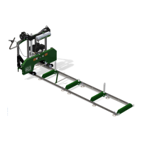
Names of Components:
The manual provides a detailed diagram of the TB23R Compact Excavator, labeling its main components:
- Canopy
- Engine Hood
- Fuel Tank
- Hydraulic Tank
- Hydraulic Pump
- Slew Motor
- Pilot Valve
- Battery
- Control Valve
- Engine
- Crawler Belt
- Idler
- Track Roller
- Shoe Slide
- Travel Motor
- Slew Bearing
- Track Adjuster
- Swivel Joint
- Bucket
- Bucket Cylinder
- Arm
- Arm Cylinder
- Boom
- Boom Cylinder
- Swing Bracket
- Swing Cylinder
- Dozer Blade
- Dozer Blade Cylinder
Standard Values and Allowable Values:
- Standard Value: The factory-set value for a new machine, serving as the target for maintenance.
- Allowable Value: The estimated use limit for a part, considering wear, deformation, and performance drop of hydraulic equipment. These values are derived from shipping standards and test results, and are to be used as a reference for servicing and judging performance, not for customer claims.
This manual serves as an essential guide for anyone involved in the maintenance and repair of the Takeuchi TB23R Compact Excavator, ensuring safe and effective servicing practices.