WIRING
6
⑧
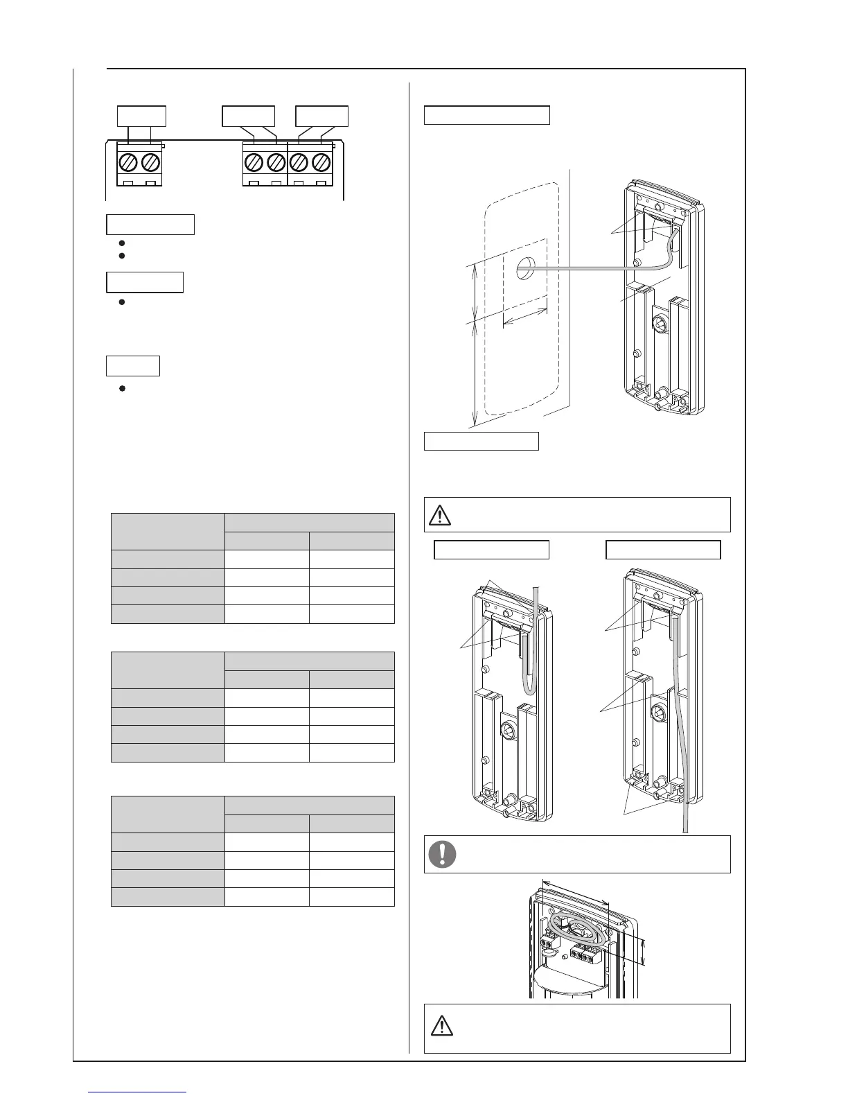
After wiring the terminal board, wind any remaining
wires into the wiring space within the sensor.
A gap remains after feeding the wiring through the wiring
hole, therefore use sealant to caulk this gap in order to
prevent the entry of insects, and to ensure waterproofing.
s
For solid wire
DC12V DC24V
φ0.5mm
φ0.65mm
φ0.9mm
φ1.2mm
2200'(670m)
3700'(1130m)
7200'(2200m)
12500'(3810m)
11000'(3400m)
18500'(5640m)
36000'(11000m)
64000'(19500m)
6-1
6-2
For external wiring, use a cable conduit and joint
box, and ensure the wiring is not exposed.
Inside
knockout
Outside knockout
Wiring
hole
Outside knockout
Wiring
hole
s
For stranded wire
Position the back of the sensor so that the wiring box is
aligned with the wiring from the wall, then feed the wiring
through the wiring hole and connect to the terminals.
6-3
For embedded wiring
Determine the path for the wiring, use nippers to break off the
outside and inside sensor knockouts to use, then feed the
wiring through the wiring hole and connect to the terminals.
For external wiring
Wiring from above Wiring from below
Wiring
hole
Wiring box
4.90"
(124.5mm)
2.09"
(53mm)
1.93"
(49mm)
Wiring space
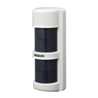
Terminal Configuration
Wiring Distance
Wiring Insertion
Supply Voltage
Power
Tamper
Tamper
Alarm
9V to 28VDC (non polarity)
Current consumption 20mA MAX
Power voltage
DC12V DC24V
2250'(686m)
3400'(1040m)
5700'(1740m)
8500'(2590m)
11000'(3400m)
17000'(5200m)
28500'(8690m)
42000'(12800m)
0.2mm
2
0.3mm
2
0.5mm
2
0.75mm
2
Power voltage
Size of wire used
Size of wire used
Alarm output
Dry contact (circut line) (N.C. only)
CONTACT CAPACITY : 30V (AC/DC), 0.1A MAX.
(resistive load)
Dry contact (semi-conductor) (N.O/N.C selectable)
CONTACT OPERATION : Reset Approx 2 sec.
CONTACT CAPACITY : 30V (AC/DC), 0.5A MAX.
(resistive load)
DC12V DC24V
2300'
3700'
5900'
9300'
11600'
18500'
29500'
46900'
AWG24
AWG22
AWG20
AWG18
s
AWG description
Power voltage
Size of wire used
Maximum wiring distance when two or more sets
are connected is the value above divided by
number of sets.
NOTE : 1)