Do you have a question about the Tamiya M-05 and is the answer not in the manual?
Overview of RC system components and recommendations for the M-05 chassis.
Information on Tamiya battery packs and chargers required for operation.
Guidance on servo dimensions compatible with the chassis for proper installation.
List of essential tools required for building the model accurately.
Important safety guidelines for model assembly and operation, covering potential hazards.
Diagram and identification of Tamiya's R/C system components, including transmitter and ESC.
Explains the function of transmitter, receiver, ESC, and servo in a 2-channel system.
Illustrates the setup and connections for a stick-type transmitter with ESC.
Read instructions thoroughly, check parts, and apply grease if needed for smooth assembly.
Step-by-step guide for assembling the right side of the chassis.
Continuation of the right chassis side assembly instructions.
Reference for installing optional upgrade parts, directing to specific pages.
Step-by-step guide for assembling the differential gear components.
Instructions for assembling the front suspension arms.
Steps for installing various gears onto the chassis assembly.
Step-by-step guide for assembling the main chassis components.
How to attach the front suspension arms to the main chassis.
Instructions for assembling the front axle components.
Steps for installing the front axles onto the chassis.
Instructions for assembling the steering linkage system.
Guide on how to attach the motor pinion gear to the motor shaft.
Guide on how to properly mount the motor onto the chassis.
Step-by-step guide for assembling the shock absorbers.
Instructions for mounting the front shock absorbers to the chassis.
Steps for connecting the rear upper suspension arms.
Instructions for assembling the rear suspension arms.
Steps for attaching the rear arms to the chassis.
Instructions for mounting the rear shock absorbers.
Connecting rear upper arms for the long wheelbase.
Continuation of the rear arm assembly process.
Further steps for attaching the rear arms to the chassis.
Instructions for mounting the rear axle assemblies.
Pre-installation checks for the radio control system.
Proper setup for antennas and power switches.
Connecting the battery and adjusting trims/servo for neutral.
Instructions for securely mounting the steering servo.
Connecting motor cables and mounting receiver/ESC.
Adjusting steering and connecting the battery.
Steps for assembling wheels, tires, and inner sponges.
Steps for mounting front and rear wheels on different chassis variants.
Instructions for installing the front body mount.
Steps for attaching rear body mounts for different wheelbase versions.
Routing the antenna and preparing the body shell.
Proper installation and care of the running battery pack.
Guidelines for safe operation of the radio-controlled car.
Correct sequence for powering up and checking the R/C system.
How to adjust steering trim for straight-line driving.
Powering off, cleaning, lubricating, and storage guidelines.
Guidance on practicing driving skills like cornering and figure-eights.
A comprehensive guide to diagnose and resolve common issues.
Steps to diagnose why the car is not moving.
Steps to diagnose loss of control or erratic behavior.
List and diagram of parts included in Bag A.
List and diagram of parts included in Bag B.
List and diagram of parts included in Bag C.
List and diagram of parts included in Bag D.
List and diagram of parts included in Bag F.
List and diagram of parts included in Bag P.
Details and diagrams of wheels, tires, and sponges.
Lists and diagrams of gear parts and the motor.
Information on caution stickers and the antenna pipe.
Components used for securing the car's body.
List of screws and small parts included in Bag A.
List of screws and small parts included in Bag B.
List of screws and small parts included in Bag C.
List of BB1 and BB2 hardware components.
List of BC1 to BC8 hardware components.
Components for drive shafts, bearings, and king pins.
Includes adjusters, O-rings, nylon bands, and tape.
| Scale | 1:10 |
|---|---|
| Product type | Car |
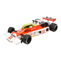
| Housing color | Yellow |
| Built-in servo | No |
| Housing material | Polycarbonate (PC) |
| Suggested gender | Boy |
| Construction type | - |
| Suitable for indoor use | Yes |
| Quantity | 1 |
| Width | 167 mm |
|---|---|
| Length | 381 mm |
| Weight | - g |
| Wheelbase | 239 mm |