MAINTENANCE
MAINTENANCE, REPLACEMENT OR REPAIR OF THE EMISSION
CONTROL DEVICES AND SYSTEM MAY BE PERFORMED BY ANY
NONROAD ENGINE REPAIR ESTABLISHMENT OR INDIVIDUAL.
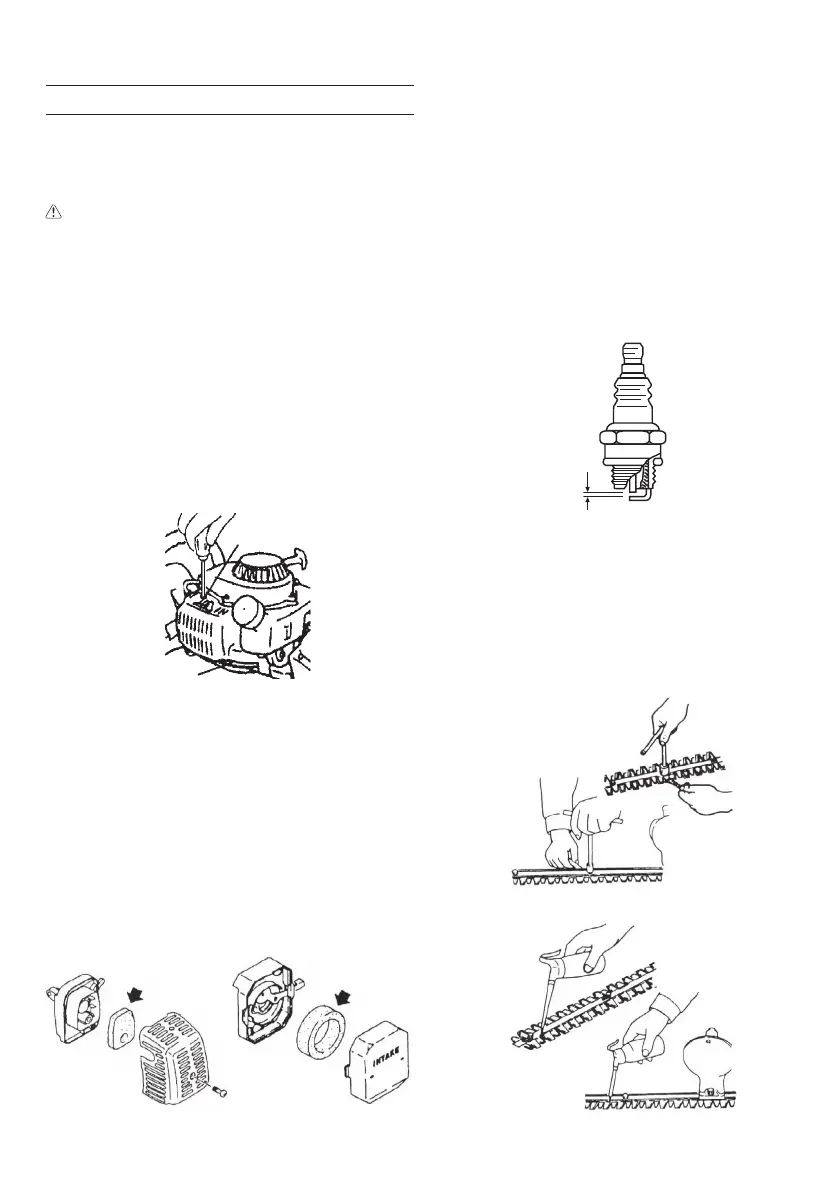
Carburetor adjustment (Fig. 13)
WARNING
○ The cutting attachment may be spinning during carburetor
adjustments.
○ Never start the engine without the complete clutch cover (15).
Otherwise the clutch can come loose and cause personal injuries.
In the carburetor, fuel is mixed with air. When the engine is test run
at the factory, the carburetor is
adjusted. A further adjustment may be
required, according to climate and altitude. The carburetor has one
adjustment possibility:
T = Idle speed adjustment screw.
Idle speed adjustment (T)
Check that the air fi lter is clean. When the idle speed is correct, the
cutting attachment will not rotate. If adjustment is required, close
(clockwise) the T-screw, with the engine running, until the cutting
attachment starts to rotate. Open (counter-clockwise) the screw until
the cutting attachment stops. You have reached the correct idle speed
when the engine runs smoothly in all positions well below the rpm when
the cutting attachment starts to rotate.
If
the cutting attachment still rotates after idle speed adjustment,
contact Tanaka dealer.
Fig. 13
Air fi lter (Fig. 14)
The air fi lter must be cleaned from dust and dirt in order to avoid:
○ Carburetor malfunctions.
○ Starting problems.
○ Engine power reduction.
○ Unnecessary wear on the engine parts.
○ Abnormal fuel consumption.
Clean the
air fi lter daily or more often if working in exceptionally dusty
areas.
Cleaning the air fi lter
Remove the air fi lter cover and the fi lter. Rinse it in warm soap suds.
Check that the fi lter is dry before reassembly. An air fi lter that has been
used for some time cannot be cleaned
completely. Therefore, it must
regularly be replaced by a new one. A damaged fi lter must always be
replaced.
Fig. 14
NOTE
Saturate the element in 2-cycle oil or the equivalent. Squeeze the
element to distribute the oil completely and to remove any excess
oil.
Spark plug (Fig. 15)
The spark plug condition
is infl uenced by:
○ An incorrect carburetor setting.
○ Wrong fuel mixture (too much oil in the gasoline).
○ A dirty air fi lter.
○ Hard running conditions (such as cold weather).
These factors cause deposits on the spark plug electrodes, which
may result in malfunction and starting diffi culties. If the engine
is low
on power, diffi cult to start or runs poorly at idling speed, always check
the spark plug fi rst. If the spark plug is dirty, clean it and check the
electrode gap. Readjust if necessary. The correct gap is 0.6 mm. The
spark plug should be replaced after about
100 operation hours or
earlier if the electrodes are badly eroded.
Fig. 15
NOTE
In some areas, local law requires using a resistor spark plug to
suppress ignition signals. If this machine was originally equipped
with resistor spark plug, use the same type of spark plug for
replacement.
Cutter blade (Fig. 16,
17)
The blades are installed to the cutter guide with the four or fi ve bolts.
Those bolts are tightened with a clearance so that the cutters can move
smoothly.
Fig. 16
Fig. 17
T
15
0.6 mm
9
000BookTHT-210BEng.indb9000BookTHT-210BEng.indb9 2009/08/188:52:242009/08/188:52:24
 Loading...