5.6 kohm to 3.3 kohm
3.3 kohm to 1.5 kohm
22 kohm to 15 kohm
100 kohm to 1.5 kohm
>5
5)
5)
>5
5)
5>
53
55
33
so
R208 to be altered from 56 ohm to 82 ohm
R209 oo
o 39 ohm to 15 ohm
R212 0
R214 o
R218
R239 o
10
2
100
200
500
1000
2000
5000
10000
20000
2-track
52 (54) dB
49 (50) dB
60 (61) dB
53 (54) dB
Signal/Tape
noise at highest speed:
4-track
DIN 45511 (weighted)
50 (52) dB
DIN 45511 (unweighted)
49 (50) dB
IEC, A-curve
58 (59) dB
IEC, unweighted
R.M.S. 53 (54) dB
500 NCO NCO
5000 10000
Fig. 8.2.
20000
50000
8.0 Modifications
8.1 Circuit Modification for Low
Noise Tape
All units with serial no higher than 2 619 561 for Mo-
del 14 and 2 515 502 for Model 15 are adjusted for
recording on Low Noise tape. This implies the fol-
lowing modifications:
A 27 ohm resistor is connected in series with C205.
The type of record/playback head has been altered
as follows:
2-track models: from 39 H to 81 H
4-track models: from 40 H to 82 H.
The equalizing coil is adjusted at 13.5 kHz, when
operating in 3
3
/
4
ips.
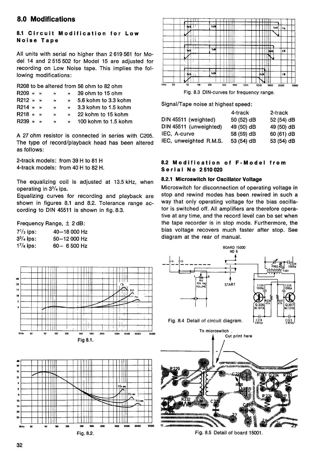
Equalizing curves for recording and playback are
shown in figures 8.1 and 8.2. Tolerance range ac-
cording to DIN 45511 is shown in fig. 8.3.
Frequency Range, ± 2 dB:
7
1
/
2
ips:
40-18 000 Hz
3
3
/
4
ips:
50-12 000 Hz
1
7
/
8
ips:
60— 6 500 Hz
10112
20
32
IIIIMIZZIL=1=1:21=EILIN:=111111
111111M112111•1110111111111111•11111111111111111
IIIMMI111=1111111111111111111INIIIIIIMIIII
=MIMI
111111111•1111111111111111•111
munrimmisimmounismminumiimm
u
1111111111E11111
1•1111•1111111•111111111111111MMIIIIIIIMENI
MIIIIIIIIIIIMM111111111111111110111=111111
Fig.
8.3 DIN-curves for frequency range.
14
•1
R6
10k log
VOLUME
4
START
10005
1000p
tir
2
3
231
4.
1
0
47k
47k
Fig. 8.4 Detail of circuit diagram.
To microswitch .
Cut print here
11....02Nowaseiseaseet,
Fig. 8.5 Detail of board 15001.
206
BC 107 B
0207
BC1 07B
C219
3300p
C2 2 3
3300p
8.2 Modification of F-Model from
Serial No 2510020
8.2.1 Microswitch for Oscillator Voltage
Microswitch for disconnection
of operating voltage in
stop and rewind modes has
been rewired in such a
way that only operating voltage
for the
bias oscilla-
tor is switched off. All amplifiers are
therefore opera-
tive
at any time, and the record level can be
set
when
the tape recorder is in stop mode. Furthermore, the
bias voltage recovers much faster after stop. See
diagram at the rear of manual.
BOARD 15000
NO 6
de
20
15
00
5
0
10 Eh
20
50
100
200
500
1000
2000
5000
10000
20000
50000
Fig 8.1.
20
IS
10
10
5-
-
IS
20
M1111111=1111111111111=M111111•1111111
1•11111111111110M1111111111111•11111111=1111111
111111=11111111IMMIIIIIIIIIIMEEIMINI
111111•11111111•1111110111111=1111115111
EMI
I
I
11111=1111111•111•111111111111•111111iiiiMMI
=1E11111111=1•1111111111111111111111111•11M
 Loading...