EasyManuals Logo

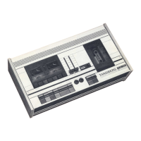
TANDBERG TCD 310 Service Manual

TANDBERG TCD 310
22 pages
To Next Page IconTo Next Page
To Previous Page IconTo Previous Page
Page #14 background imageLoading...
Page #14 background image
5.
ELECTRICAL
ADJUSTMENTS
GENERAL
.
NECESSARY
EQUIPMENT
”0
dB”
level
is
defined
as
775
mV.
Thus
—5
dB
2high
impedance
voltmeters
(do
NOT
use
equals
450
mV
and
—35
dB
equals
14
mV.
universal
meters).
Frequency
counter.
; .
;
;
Audio
generator.
Make
the
adjustments
in
the
order
in
which
they
are
listed
here.
Many
of
the
adjustments
require
that
previous
adjustments
have
already
been
Wow
meter
(required
for
wow
test
only).
correctly
made.
It
is
especially
important
that
adjustment
for
CrOg
tape
be
made
before
adjust-
ment
for
HL
tape.
Tandberg
test
tapes
No.
21
(1,000
Hz
speed
test),
No.
22
(3,150
Hz
wow
test),
No.
23
(6,300
Hz
azimuth
test)
and
No.
24
(1,000
Hz
playback
level).
TDK
C60
CHROM
or
equivalent
chromium
dioxide
cassette.
Distortion
meter.
Hum/noise
meter
(required
for
signal/noise
test).
Clean
and
degauss
the
tape
path
before
and
after
the
adjustments.
It
is
assumed
that
the
tape
path
has
already
been
correctly
adjusted
as
described
on
pages
5,
6
and
7.
Maxell
C60
UD
or
equivalent
HL
cassette.
Location
of
test
points
and
adjustable
components:
see
page
17
Azimuth
Adjust
to
best
signal.
Difference
screw
on
|compromise
between
the
tracks:
|
head
<
4¢dB
1775
mV
R317
(left
ch.)
R417
(right
ch.
Playback
c
+
1%
(990
1010)
Playback
S
0.2%
Measure
at
end
of
{DIN
45,507
tape.
Measure
both
peak
weighted)
in
vertical
and
hori-
45.507)
zontal
position
CrO2
Frequency
|Connect
80
-
100
kHz
Connection
is
made
Recording
counter
inductively
with
a
coil
or
a
few
to
erase
turns
of
ordinary
head
(see
wire.
Instead
of
a
comments)
frequency
counter
a
long-wave
receiver
(
tuned
to
3rd
har-
monic)
can
be
used
|
CrO2
Voltmeter
[Across
[28
32
V
Recording
lerase
head
CrO2
Voltmeters
[OUTPUT
|<
5
mv
lps
INPUT
sockets
open
|
Recording
|
sockets
=
CrO2
Voltmeters
[R319
(left)
[Minimum
L301
{left
ch.)
|
The
filters
prevent
Recording
R419
(right)|reading
L401
(right
ch.)
|
the
record
amplifiers
to
ground
\{2—4
V}
from
short-circuiting
the
bias
voltage
to
ground
130!
-===4
TO
REC
/PLAY
HEAD
TO
OUTPUT
OF
REC
AMP
cH
RTS

Questions and Answers:

Question and Answer IconNeed help?

Do you have a question about the TANDBERG TCD 310 and is the answer not in the manual?

TANDBERG TCD 310 Specifications

General IconGeneral
Weight7.5kg
Track System4-track, 2-channel stereo
Tape Speed4.76 cm/s
Heads1 x record/playback, 1 x erase
TypeCassette Deck
Frequency Response30 Hz to 16 kHz (Chrome tape)
Signal to Noise Ratio58dB
Wow and Flutter0.07 %
MotorDC servo motor
Tape TypeCrO2
Power Supply220V
InputLine In

Related product manuals