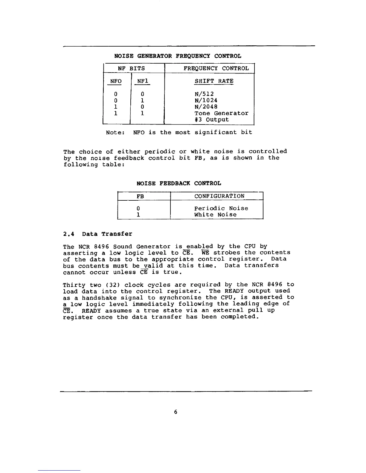
NOISE GENERATOR FREQUENCY CONTROL
NF BITS
NFO
0
0
1
1
NF1
0
1
0
1
FREQUENCY CONTROL
SHIFT RATE
N/512
N/1024
N/2048
Tone Generator
#3 Output
Note:
NFO is the most significant bit
The choice of either periodic or white noise is controlled
by the noise feedback control bit FB, as is shown in the
following table:
NOISE FEEDBACK CONTROL
FB
0
1
CONFIGURATION
Periodic Noise
White Noise
2.4 Data Transfer
The NCR 8496 Sound Generator is_enabled by the CPU by
asserting a low logic level to CE. WE strobes the contents
of the data bus to the appropriate control register. Data
bus contents must be_valid at this time. Data transfers
cannot occur unless CE is true.
Thirty two (32) clock cycles are required by the NCR 8496 to
load data into the control register. The READY output used
as a handshake signal to synchronize the CPU, is asserted to
a low logic level immediately following the leading edge of
CE.
READY assumes a true state via an external pull up
register once the data transfer has been completed.
 Loading...