•
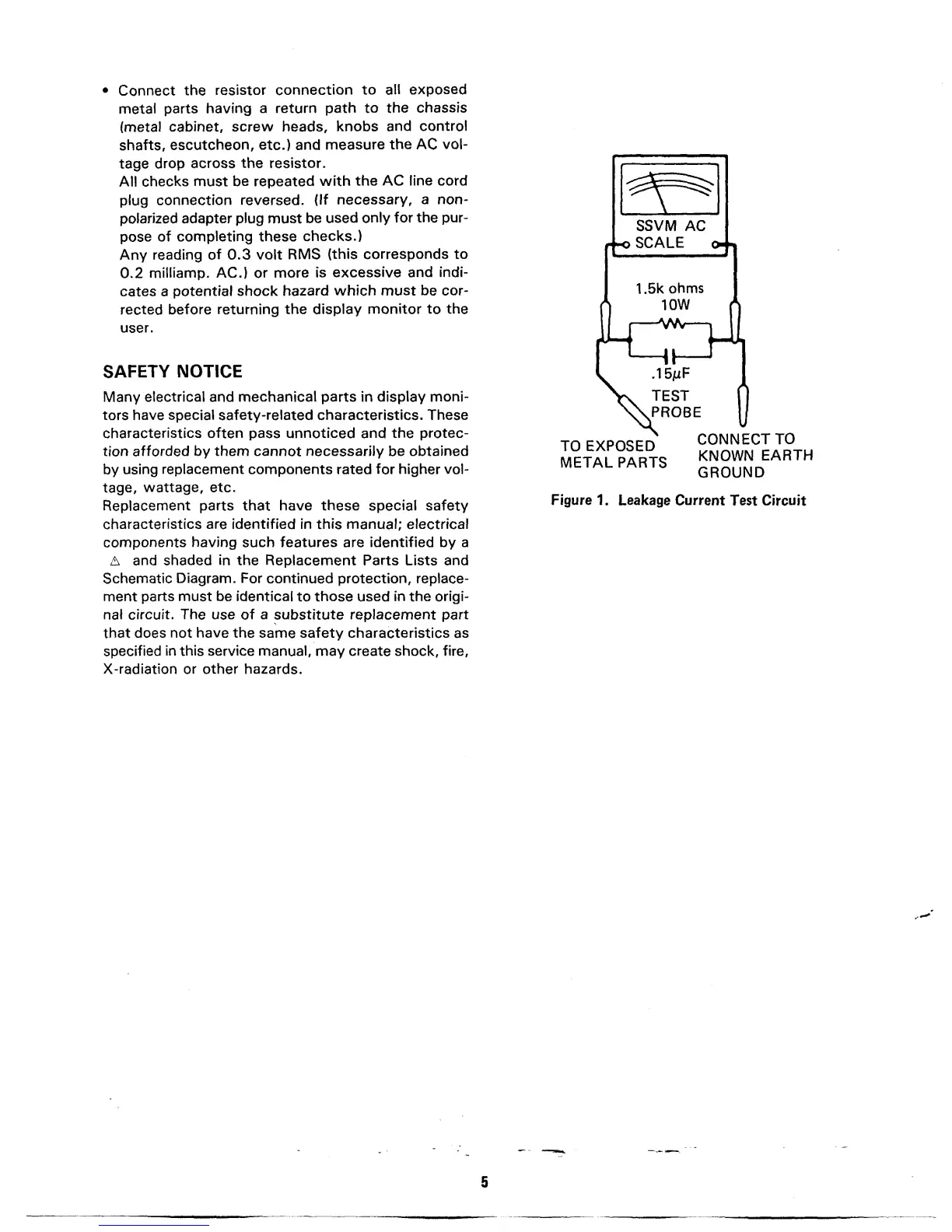
Connect
the
resistor connection
to
all
exposed
metal
parts
having
a return path to
the
chassis
(metal
cabinet,
screw
heads,
knobs
and
control
shafts,
escutcheon, etc.) and
measure
the
AC
vol-
tage
drop across
the resistor.
All
checks must
be repeated
with
the
AC line cord
plug
connection reversed.
(If
necessary, a non-
polarized adapter
plug
must
be
used
only for
the pur-
pose
of
completing
these
checks.)
Any
reading
of 0.3 volt
RMS
(this
corresponds
to
0.2
milliamp.
AC.) or
more
is
excessive
and indi-
cates a
potential shock
hazard which must
be cor-
rected
before
returning
the display
monitor to
the
user.
SAFETY
NOTICE
Many
electrical and
mechanical
parts in display
moni-
tors
have special safety-related characteristics.
These
characteristics often
pass
unnoticed and
the protec-
tion
afforded by them cannot necessarily
be
obtained
by
using
replacement
components rated for higher vol-
tage,
wattage,
etc.
Replacement
parts
that
have these
special
safety
characteristics are identified in
this manual; electrical
components
having
such
features
are
identified by a
A
and shaded
in
the Replacement Parts Lists and
Schematic
Diagram. For
continued protection, replace-
ment
parts must
be identical
to
those
used
in the
origi-
nal
circuit. The use
of
a
substitute replacement part
that
does not
have
the same safety characteristics
as
specified
in this service
manual, may create shock,
fire,
X-radiation or other hazards.
TO
EXPOSED
METAL PARTS
CONNECT
TO
KNOWN
EARTH
GROUND
Figure
1. Leakage Current
Test
Circuit