3,
Vertical
Deflection
Circuit
The
vertical
sync,
signal
with
positive polarity
is ap-
plied
to
pin(7)of
the vertical
and
horizontal
IC
(IC601).
Pin
(8)of
IC601
is connected
to
the vertical oscillator
circuit.
The
frequency of the oscillator can
be
con-
trolled
by the
voltage
of pin
(8)
which
can be varied
by
V.HOLD
VR
(R514).
The
sawtooth signal is
ob-
tained by
the integrating
circuit which
is connected be-
tween
pin
(5)
and pin
Qj)
.
The
oscillator output
is
fed
to the vertical
drive circuit
through a
buffer
circuit.
Its
output, derived
from pin
(2)
,
is
applied to
the
vertical output.
The
sawtooth
wave
is
applied
to
pin
(3)
of
IC601 as
an AC
feedback
signal.
The
emitter circuit of Q501 is controlled by
V-SIZE VR
(R507)
to vary the vertical size of the raster.
The
vertical
linearity
control
(R526) is part of
an
in-
tegrating circuit
which controls the sawtooth
waveform.
4.
Horizontal
Oscillator, AFC
and
Drive Circuit
The
horizontal
sync,
signal
with
positive
polarity is ap-
plied to
pin
(15)
of IC601.
The output
from the fly-back
transformer (T602)
is
in-
tegrated
and
connected
to pin
(^3)
of
IC601 as part
of
the
automatic frequency control circuit.
H.
CENT
control
(R623)
determines
the relative posi-
tion
of
the raster and
picture.
The
horizontal
oscillation
frequency can
be controlled
by H.
HOLD VR
R607
connected
to
pin
(j~2).
The
horizontal frequency is
obtained from pin
\[Q)
of
IC601,
and is
fed
to
the
next
horizontal
drive circuit.
The
pulse-switching
mode of the
driver and
output
stage is a
reverse
polarity
type;
that
is,
when
the
driver
transistor
Q601 is
ON,
the
output
transistor
Q602
is
OFF.
5.
Horizontal Output
and
HV
Rectifier
(Figs.
3-5)
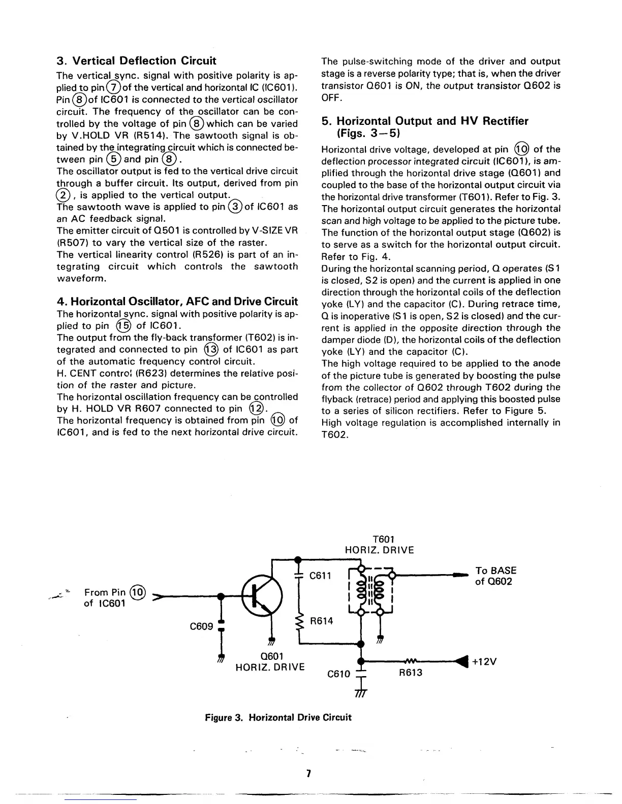
Horizontal drive voltage,
developed at
pin
^6)
of
the
deflection
processor integrated
circuit
(IC601
),
is
am-
plified
through
the horizontal drive
stage
(Q601)
and
coupled to the base
of
the horizontal output
circuit
via
the horizontal drive transformer
(T601 ).
Refer
to
Fig. 3.
The horizontal
output circuit generates the
horizontal
scan and
high voltage
to
be applied to
the picture tube.
The function
of the
horizontal output
stage
(Q602)
is
to
serve
as a
switch for the horizontal
output
circuit.
Refer
to
Fig. 4.
During
the horizontal
scanning
period, Q
operates
(S
1
is
closed,
S2 is open) and the current
is
applied
in
one
direction through the
horizontal coils
of the
deflection
yoke
(LY)
and the
capacitor
(C).
During retrace
time,
Q is inoperative (S 1
is
open, S2 is
closed)
and
the
cur-
rent is applied in the opposite
direction
through
the
damper
diode
(D),
the horizontal
coils of
the
deflection
yoke (LY)
and
the capacitor
(C).
The
high
voltage
required
to
be
applied
to
the
anode
of the picture tube is generated by
boosting
the
pulse
from the collector of Q602
through
T602
during
the
flyback
(retrace) period and applying
this
boosted
pulse
to
a
series of
silicon
rectifiers. Refer
to
Figure 5.
High voltage regulation is accomplished
internally
in
T602.
T601
HORIZ. DRIVE
From
Pin (TS)
^
of
IC601
^
C609
T
I
To
BASE
of
Q602
Q601
HORIZ.
DRIVE
^+12V
Figure
3.
Horizontal
Drive Circuit