THEORY
OF
OPERATION
1.
RGB
Drive Circuit
IC451 is a linear
IC
to
amplify
the
RGB
signals.
The DC
restoration
system
of
IC451 provides
control
of
the
simultaneous
amplitude
(contrast)
and DC level
(brightness)
of
RGB
.
The
synchronizing
signal, as a DC restoration pulse, is
fed
from
pin @
of
IC601
to
pins @ and @
of
IC451.
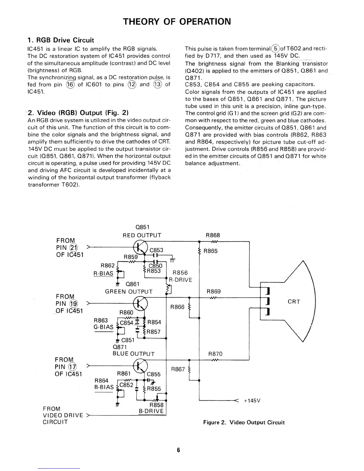
· 2. Video (RGB) Output (Fig. 2)
An
RGB
drive
system
is
util
ized in
the
video
output
cir-
cuit
of
this
unit. The
function
of
this
circuit
is
to
com-
bine
the
color
signals and
the
brightness
signal, and
amplify
them
sufficiently
to
drive
the
cathodes
of
CRT.
145V
DC
must
be applied
to
the
output
transistor
cir-
cuit
(0851,
0861,
0871).
When
the
horizontal
output
circuit
is operating, a pulse used
for
providing
145V
DC
and
driving
AFC
circuit
is developed
incidentally
at a
winding
of
the
horizontal
output
transformer
(flyback
transformer
T602).
0851
RED
OUTPUT
FROM
PIN@
OF
IC451
R862
R-BIAS
This pulse is taken
from
terminal
@
ofT602
and recti-
fied by
D717
, and
then
used as
145V
DC.
--··-
-
The
brightness
signal
from
the
Blanking
transistor
(0402)
is applied
to
the
emitters
of
0851,
0861
and
0871.
C853,
C854
and
C855
are
peaking
capacitors.
Color signals
from
the
outputs
of
IC451 are applied
to
the
bases
of
0851
,
0861
and
0871
. The
picture
tube
used in
this
unit
is a precision, inline
gun
-
type.
The control
gr
id
(G
1)
and the screen grid (G2) are com-
mon
with
respect
to
the
red, green and blue cathodes.
Consequently, the
emitter
circuits
of
0851,
0861
and
0871
are
provided
with
bias
controls
(R862
,
R863
and
R864,
respectively)
for
picture
tube
cut-off
ad-
justment.
Drive
controls
(R856
and
R858)
are provid-
ed in
the
emitter
circuits
of
0851
and
0871
for
white
balance
adjustment.
R868
R865
R856
0861
R-DRIVE
R869
FROM
PIN@)
CRT
R866
OF
IC451
R863
G-BIAS
C851
0871
BLUE
OUTPUT
R870
FROM
PIN@
R867
OF
IC451
R861
R864
C852
B-BIAS
---
+145V
FROM
R858
B-DRIVE
VIDEO
DRIVE
CIRCUIT
Figure 2.
Video
Output
Circuit
6