4.7: TRIM CONTROLS
The primary function of the trim controls is to compensate for room effects. How a monitoring system sounds and measures is
obviously affected by room acoustics, a major factor being the monitor's proximity to boundaries. If placed close to a wall the
main effect is a low frequency boost. In a common set-up, where the mixing desk and monitors are located close to a wall or
studio window, the LF boost can be as high as 6dB (relative to free space), and this boost happens progressively from 400Hz
downwards.
To enable precise compensation for room related effect, and to correct slight variations in drive unit sensitivity, a three-band
equalizer precedes the crossover section, allowing fine adjustment at a low Q. For example, the mid trim has a +/- 2dB range
of adjustment centred at 1.4 kHz. Yet because of the low Q factor this is still providing a +/- 1dB adjustment at 330Hz and
6kHz.
There is a further option to reduce LF output using the foam bungs provided to disable the bass reflex ports. In a ported enclosure
system such as the Ellipse, the ports add to the LF acoustic output, but they do this by resonance. With the ports disabled, the
enclosure becomes an "infinite baffle" system, which has a superior transient response. So there is a trade-off to experiment with.
For example, some users will prefer the sound with the ports disabled and the low trim turned up, rather than the ports enabled
and the low trim turned down. Minimum and maximum levels of LF output are achieved with the low trim turned to -3dB and
the ports disabled; versus having the low trim turned to +3dB and the ports enabled. But as suggested above, it is possible to
get similar (but not identical) output curves with ports disabled or enabled, using the low trim adjustment.
5.0: PERFORMANCE DATA
Frequency response measurements have been measured in Tannoy's anechoic chamber @ 1 metre on-axis (apart from dispersion
traces). Some measurements taken with ports disabled by use of port bungs - see individual captions.
In common with all conventional anechoic chambers, the benefits are limited by the physical size of the space, hence the
irregularities in the traces below 200Hz. To maintain anechoic performance down to 20Hz would require a space maybe 100
times larger, which becomes unfeasible. Also, a true full bandwidth anechoic chamber would show much reduced output at low
frequency, a factor of the wider dispersion of longer wavelengths. Virtually all real-world acoustic spaces will show higher low
frequency levels than our anechoic chamber.
13
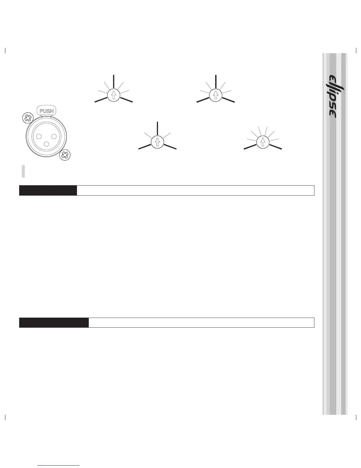
Fig. 5.
XLR signal input socket - Sensitivity control and Lo. Mid and Hi Trim adjuster pots
+4db -10db
Sensitivity
-3db
Hi Trim
+3db
-2db
+2db
Mid Trim
-3db
Lo Trim
+3db
Pin 2
Pin 3
SIGNAL INPUT
+Ve :
-Ve :
Gnd :
Pin 1
 Loading...