9
3.4: SETTING THE LEVEL
The sensitivity control allows for use with a wide range of equipment. Although the two signal levels widely used are nominally
+4dBu and -10dBu, the whole area of reference levels is highly confused, with different levels being adopted by different
manufacturers, broadcasters, countries, types (e.g. pro or semi-pro) etc. etc. One well-known and high quality mixer manufacturer
uses the 0dB meter indication to denote 0dBu output signal level (0.775V). The control room monitor level control can then add
up to 10dB gain; so that, with the control room level control set to maximum, 0dB on the meters would mean sending +10dBu
(2.45V) to the monitors.
Fortunately, there is a simple way to ignore all that and set the sensitivity control to suit your own mixing desk / workstation etc.
Basically, when running with a healthy level on the master output meters, peaking at around, say +3dB (on some thumping
dance music for instance), your Ellipse monitors should be able to reach full output in their +4dB setting (minimum). If not,
although your monitor level control is turned up to maximum, increase the sensitivity gradually (clockwise towards the -10dB
end) until you see short flashes of the red clip indicator.
You can now turn down the volume knowing that max output from your equipment results in flat-out running of your monitors,
so they are correctly matched. A little fine-tuning to ensure the left and right are set equally is the only other thing to check.
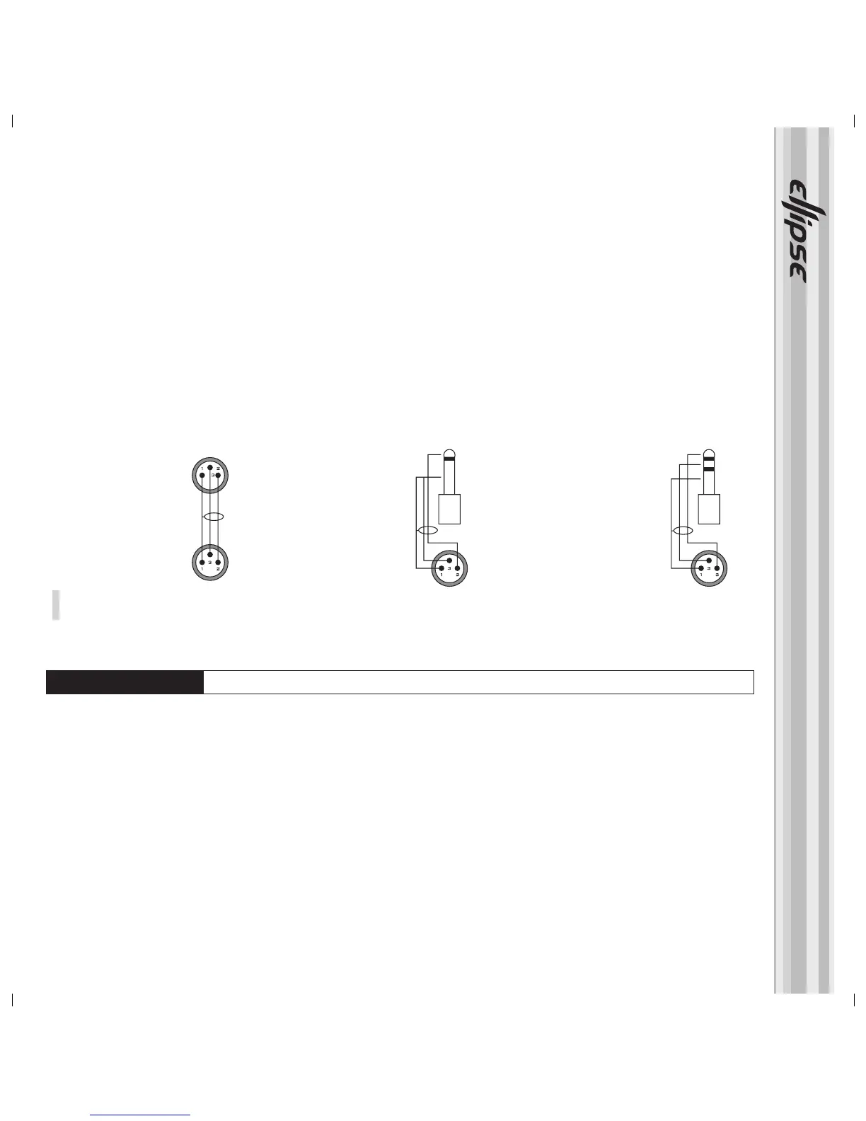
If the source itself has a balanced output, use a standard screened (shielded) twin conductor microphone cable, connected as
follows:
Pin 1 female to pin 1 male (using the screen)
Pin 2 female to pin 2 male
Pin 3 female to pin 3 male
If the source has an unbalanced output, a single conductor screened cable can be used as follows: Signal and ground (screen) wired
as normal at the source connector; at the XLR end, the signal should be connected to pin 2, and the screen to pins 1 AND 3.
However, rejection of EMI (Electro-Magnetic Interference, such as radio breakthrough) can be improved by using a screened
twin conductor cable even with an unbalanced source, with male XLR connection as described above, as follows: At the source
end, whether a phono (RCA) or jack type of connector, the signal (+) should be connected to the centre pin, and the screen
and signal (-) should be linked and connected to the signal ground. (See fig.4)
Fig. 4.
XLR signal input socket - Sensitivity control and Lo. Mid and Hi Trim adjuster pots
XLR - XLR
Pin 1 - Pin 1 (Ground)
Pin 2 - Pin 2 (Hot)
Pin 3 - Pin 3 (Cold)
Jack (unbalanced) - XLR
Sleeve - Pin 1 (Ground)
Tip - Pin 2 (Hot)
Sleeve - Pin 3 (Cold)
Jack (balanced) - XLR
Sleeve - Pin 1 (Ground)
Tip - Pin 2 (Hot)
Sleeve - Pin 3 (Cold)
TIP
GND
TIP
GND
RING
 Loading...