1. Introduction
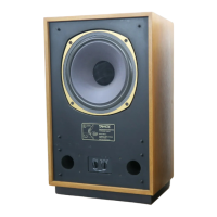
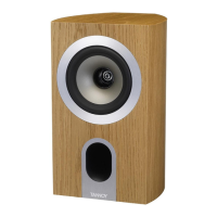
The Tannoy i5 AW has been designed to be both sonically and cosmetically pleasing
for all applications ranging from background music in a restaurant to live keyboard
monitoring on stage.
ICT
TM
or Inductive Coupling Technology utilises a wireless electromagnetic tweeter
that does not require a crossover and cannot be burned out from heavy or abusive
use. The 1" aluminium high frequency dom e has a deep drawn skirt which sits on the
inside of the low frequency voice coil in the same magnetic gap. The skirt is like a
single shorted turn, which is induced with high frequency information generated by
the low frequency voice coil, which is fed a full bandwidth signal. The ICT
TM
dome is
at the heart of our i5 AW transducer which utilises a moulded plastic cone and nitryl
rubber surround to further enhance its' durability and long term reliability.
The ICT
TM
driver is housed in a plastic enclosure that has been optimally tuned to
achieve maximum bass response and tonal balance.
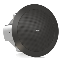
For applications requiring extended low frequency enhancement, a range of Tannoy
sub-bass systems are available and can be used in conjunction with the i5 AW.
The i5 AW is also available as a Transformer version (i5T AW), for use from 70.7V or
100V line systems
2. Unpacking
Every Tannoy i5 AW is carefully inspected before packing. After unpacking, please
inspect for any exterior physical damage, and save the carton and an y relevant
packaging materials in case the loudspeaker again requires packing and shipping. In
the event that damage has been sustained in transit notify your dealer immediately.
3. Connectors/Cabling
The i5 AW has two spring-loaded terminals for connec tion to the amplifier. These
terminals are capable of accepting cables with conductor diameter of up to 6mm.
Red is Positive
Black is Negative
Cable choice consists mainly of selecting the correct cross -sectional area in relation
to the cable lengt h and the load impedance. A small cross -sectional area would
increase the cables' series resistance, inducing power loss and response variations
(damping factor).
Connectors should be wired with a minimum of 2.5 mm
2
(12 gauge) cable. This will
be perfectly satisfactory under normal conditions. In the case of very long cable runs
the wire size should exceed this, refer to the following table for guidance: -
CABLE RUN
(m)
C.S.A. OF EACH
CONDUCTOR (mm)
CABLE
RESISTANCE Ω
% POWER LOSS
INTO 8Ω LOAD
% POWER LOSS
INTO 4Ω LOAD
10 2.5
4.0
6.0
0.14
0.09
0.06
1.7
1.1
0.73
3.5
2.2
1.5
25 2.5
4.0
6.0
0.35
0.22
0.14
4.3
2.7
1.8
8.6
5.4
3.6
50 2.5
4.0
6.0
0.69
0.43
0.29
8.6
5.4
3.6
17.0
11.0
7.2
100 2.5
4.0
6.0
1.38
0.86
0.58
17.0
11.0
7.2
35.0
22.0
14.0

 Loading...