3. Connectors / Cabling
VX Series Operation Manual rev 3.0.0
5
3. Connectors / Cabling
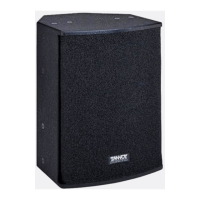
On VX Series loudspeakers, connector types available vary by model, as detailed below:
VX 5.2, VX 6, VX 8
Inputs on 1 x speakON® 4-pole, 1x binding post pair. Binding posts are connected in parallel to speakON® 1+
and 1-. Not bi-amp capable.
VX 8M
Inputs on 2 paralleled speakON 4 pole connectors. Not bi-amp capable
VX 8.2, VX 12
Inputs on 2 x speakON® 4-pole and 2 x barrier strip terminals. Both barrier strip terminal pairs are connected in
parallel to speakON® poles 1+ and 1-. Not bi-amp capable.
VX 12HP, VX 12Q, VX 12.2Q, VX 15HP, VX 15Q
Inputs on 2 x speakON® 4-pole and 2x barrier strip terminal pair. Both barrier strip terminal pairs are connected
in parallel to speakON® poles 1+ and 1- when congured for full range operation. Bi-amp conguration may be
implemented using speakON® connectors only. (See 6.0 below.)
Binding post terminals are capable of accepting cables with a conductor of up to 6 mm sq CSA (AWG 10). Red is positive
and black is negative.
Barrier strips accept wire up to 4 mm sq CSA (AWG 12). Barrier strip polarity is as indicated.
The speakON® connectors will accept wire up to 4 mm sq CSA (AWG 12) with an outside diameter of up to 15 mm and
a current rating of 30 A. When so equipped, the pins of the two speakON® sockets identied input/output on the rear
of the input panel are paralleled within the enclosure. Tannoy have adopted the conventional wiring standard for the VX
Series product: pin 1+ is positive pin 1- is negative. For a worldwide list of Neutrik® distributors see www.neutrik.com.
When choosing cable type, it is important select the correct cross sectional area in relation to the cable length and
the load impedance. A small cross sectional area will increase the cable’s series resistance, inducing power loss and
response variations (damping factor). Connectors wired with 2.5 sq. mm (12 gauge) cable will be satisfactory under normal
conditions; with very long cable runs, the wire size should be increased. Please refer to the following table for guidance:
Cable run (m)
C.S.A of Each
Conductor
Cable resistance
(ohms)
% Power loss
into 8 ohms
load
% Power loss
into 4 ohms
load
10
2.5
4.0
6.0
0.14
0.09
0.06
1.7
1.1
0.73
3.5
2.2
1.5
25
2.5
4.0
6.0
0.14
0.09
0.06
1.7
1.1
0.73
3.5
2.2
1.5
50
2.5
4.0
6.0
0.14
0.09
0.06
1.7
1.1
0.73
3.5
2.2
1.5
100
2.5
4.0
6.0
0.14
0.09
0.06
1.7
1.1
0.73
3.5
2.2
1.5
 Loading...