© Copyright (2021) All rights reserved. Changes, which serve technical improvements are reserved.
4
PRSU Series, Operating Instructions Manual (Revision 1.0)
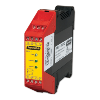
PRSU/4 Electrical Overview
The PRSU/4 can be operated with an input voltage of +24VDC, or 24VAC. This model
features three normally-open safety relays that are triggered by the “Sensor Monitoring”
terminals (S11, S12, S21, S22). This model also features an additional normally-closed
auxiliary relay (not for safety use).
Power input (+24VDC, or 24V
AC
)
Power input (GND, or 24V
AC
)
Auxiliary Relay (Non-Safety)
Figure 2: Functional Schematic (PRSU/4)
Table 2: Device Terminals (PRSU/4)