33
Diagram 3 Parts List – Handle Group, 1.5 hp Electric
ITEM P/N DESCRIPTION QTY
1 ------ Handle Assembly – Electric 1
2 177786 Adjustable Handle Weldment 1
3 139568 Grip, Handle 2
4 177838 Switch Box Weldment 1
5 020742 Washer, Flat .313 Dia 2
6 173019 Lockwasher, External Tooth, M8 3
7 197227 Capscrew, Hex Hd M8 x 1.25 x 20mm 2
8 177747 Rocker Switch, 20A/1.5hp 1
9 182024 Strain Relief, 3/4 NPT 2
10 177746 Nylon Locknut, 3/4 NPT 2
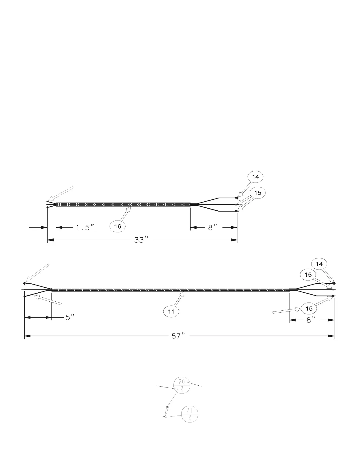
11 177886 Electrical Cord, SO/SOW, 12/3 x 57 Inches 1
12 172028 Capscrew, Hex Hd M8 x 1.25 x 16mm (Full Thread) 1
13 197101 Wire Tie, .094 x 8.0 Lg (Thru Front Of Handle) 1
14 177288 Wire Connector, .312 Terminal Ring 2
15 167703 Wire Connector, .25 Female, Quick Connector 4
16 177885 Electrical Cord, SO/SOW, 12/3 x 33 Inches 1
Callout Designation:
On The Diagram.
QTY
The Quantity only at this location.
This the total quantity used
throughout the entire diagram.
is not
Bare Wires (3) Attached To Plug
(Diagram 1, Item 40)
Item 15 To Black
& White Wires
(Attaches To Switch
-Item 8)
Item 14 To Green Wire (Ground)
(Attaches To Switch Box-Item 4, Using Items 6 & 12)
P/N 046422 Ring Terminal-#10
ttached To Green Wire (Ground)
(Attaches To Motor)
Black & White Wires-Strip Ends
(No Connector) (Attaches To Motor)
Item 15 To Black Wire
(Attaches To Switch-Item 8)
Item 15 To White Wire
(Attaches To Switch-Item 8)
Item 14 To Green Wire (Ground)
(Attaches To Switch Box-Item 4, Using Items 6 & 12)