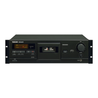
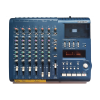
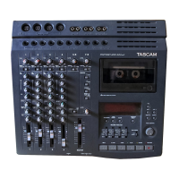
Do you have a question about the Tascam 133-B and is the answer not in the manual?
Outlines control operations, keys, and controller interaction with multiplexers for system control.
Details pin assignments, logic diagram, and truth table for the multiplexer IC U912.
Explains the multiplexer for auto-present switches, including pin assignments, logic diagram, and truth table.
Describes the microprocessor-based controller, its pin assignments, and overall operation.
Presents the block diagram of the controller LSI, illustrating its internal components and data flow.
Details the controller's program structure and function addresses, mapping control signals to specific operations.
Illustrates the timing of control signals in relation to operating commands for tape drive and amplifier control.
Details the motor reversing IC, its pin assignments, block diagram, and truth table for operation.
Explains the system controller's operation, including the clock circuit and overall timing.
Describes the initial reset circuit that ensures proper deck operation upon power-up.
Explains the command input circuit, connecting multiplexers, keys, and switches to the controller.
Explains the operation of solenoid drive circuits, including the fast solenoid drive circuit.
Describes the head base solenoid drive circuit and its operation during various playback modes.
Details the pinch roller solenoid drive circuit, explaining its function and operation.
Covers the reel motor drive circuit, explaining motor rotation and its control mechanisms.
Explains the motor drive circuit, detailing input signals and motor reversing operations.
Describes the capstan motor drive circuit, its operation during playback modes, and speed selection.
Explains the tape counter, its components like photocouplers, and tape travel direction detection.
Details the CUE signal reproducing circuit, explaining its components and operation.
Describes the CUE signal output circuit, explaining its gain and muting function.
Explains the CUE signal peak level meter circuit, detailing play and record peak level measurement.
Details the CUE signal recording circuit, covering its components and signal processing for recording.
Explains the 25 Hz CUE signal generating circuit, including its components and oscillator frequency.
Explains the Auto-Present system's functions like automatic stopping and repeating playback based on CUE/REW switches.
Details the procedure for positioning the head base plate and adjusting the solenoid for proper clearance.
Explains how to adjust the clearance for microswitch (A), ensuring proper contact with the safety lever.
Details the adjustment of clearance for microswitch (B), ensuring contact with the eject lever.
Describes the procedure for adjusting the capstan assembly thrust to within specified limits.
Explains how to adjust take-up torque to stabilize tape travel and reduce speed variations.
Details how to measure and adjust fast forward and rewind torque for optimal tape handling.
Explains the adjustment of pinch roller pressure to stabilize tape travel and reduce speed variations.
Covers the procedure for checking and adjusting tape speed using test tapes and a frequency counter.
Provides guidelines for measuring wow and flutter, including methods and necessary settings.
Details the procedure for checking and adjusting playback level using test tapes and a level meter.
Explains how to check and adjust VU meter and CUE meter readings using test tapes.
Describes how to check and adjust playback frequency response using test tapes and variable resistors.
Explains the adjustment of bias dummy coils to set the correct bias frequency for recording.
Details the adjustment of bias filters to minimize bias signal leakage to the output terminals.
Covers the adjustment of monitor meters, including input and output level settings.
Explains the adjustment of bias traps to minimize meter readings by tuning specific inductors.
Provides preparation steps and procedures for adjusting the bias level for optimal recording performance.
Details the procedure for setting and adjusting the recording level, including Dolby level settings.
Explains how to check and adjust the overall frequency response across different tape speeds.
Covers the procedure for measuring and calculating the overall signal-to-noise ratio, including setup steps.
Describes the procedure for measuring overall distortion using specific instruments and setup.
Presents the first exploded view and parts list, detailing assembly components and their references.
Details the fourth exploded view and parts list, showing assembly components and their part numbers.
Presents the third exploded view and parts list, illustrating assembly components and their references.
Lists miscellaneous components used in the OSC PCB 107 assembly.
Provides the parts list for the OSC PCB 107 assembly.
Lists the parts for the Joint PCB 123 assembly.
Details the parts list for the Phone Amplifier PCB assembly.
Lists the part numbers and descriptions for trimmer capacitors used in the unit.
Provides the parts list for the Power Supply PCB assembly.
Lists the parts for the Control PCB assembly.
Details the parts list for the Muting PCB assembly.
Provides the parts list for the Remote PCB 111 assembly.
Lists the components for the Balance Amplifier PCB assembly.
Lists components for the Switch PCB 174 Assy (PC Board Omitted).
Lists components for the Phones Jack PCB 102 Assy (PC Board Omitted).
Lists components for the Switch PCB 175 Assy (PC Board Omitted).
Lists components for the Counter PCB 103 Assy (PC Board Omitted).
Lists components for the Mic Jack 109 Assy (PC Board Omitted).
Instructions for altering AC power settings for general export models.
Notes for U.K. customers regarding plug installation and mains lead wire colors.
Provides the schematic diagram for the amplifier section of the TASCAM 133-B.
Presents the schematic diagram for the tape transport mechanism of the TASCAM 133-B.
| Brand | Tascam |
|---|---|
| Model | 133-B |
| Category | Cassette Player |
| Language | English |