EasyManua.ls Logo

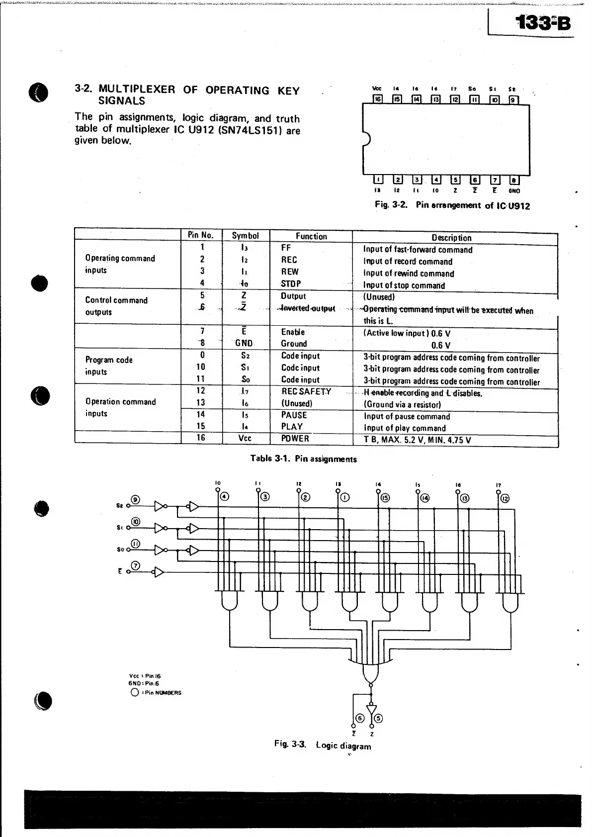
Tascam 133-B - 3-2. MULTIPLEXER OF OPERATING KEY SIGNALS

Tascam 133-B
66 pages
Print Icon
To Next Page IconTo Next Page
To Previous Page IconTo Previous Page
Loading...
it
iat
a
aN
atari
a
2”
.
aa
bindu
stliban
dain
ts
sada.
‘ z
Lacie
en
sins
si
hatis
Nias
at
tatetmsbscacahlaailawisthdinta
ci
ethisteCis
Album
settable
se
AbERLilae
os
mabe
ditatee
tid
die
dacaciatRn
tine
dames
¢
svar
all
pO
ALi
iTS
ie
a
SNe
cai
eu
UREN
CRRA
Nada
SA
Saba
fc
inna
ta
heck
tals
iat
isa
tla
tea
UMS
Aubin
btn
atch
a
133-8
&
3-2.
MULTIPLEXER
OF
OPERATING
KEY
SIGNALS
_
The
pin
assignments,
logic
diagram,
and
truth
table
of
multiplexer
IC
U912
(SN74LS151)
are
given
below.
ia
2
ot
io
862
Z
E
ono
.
Fig.
3-2.
Pin
arrangement
of
IC-U912
Description
Input
of
fast-forward
command
Input
of
record
command
Input
of
rewind
command
Input
of
stop
commatid
(Unused)
--@perating
command
input
willbe
executed
when
this
is
L.
(Active
low
input)
0.6
V
0.6V
3-bit
program
address
code
coming
from
controller
3-bit
program
address
code
coming
from
controller
Operating
command
inputs.
Dutput
4
edaverted-
output
—-
Control
command
outputs
Code
input
Codc
input
Code
input
Program
code
inputs
Operation
command
inputs
Input
of
pause
command
Input
of
play
command
TB,
MAX.
5.2
V,
MIN.
4.75
V
Vee
=
Pin
I6
6NO:Pin.6
©
=
Pin
NUMBERS
@
Fig.
3-3,
Logic
diagram