Do you have a question about the Tascam 122 and is the answer not in the manual?
Details mechanical aspects like tape speed, dimensions, and weight.
Details electrical characteristics including input/output levels, frequency response, and distortion.
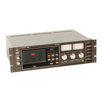
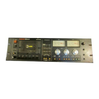
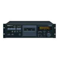
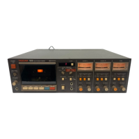
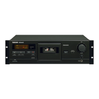
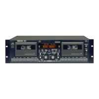
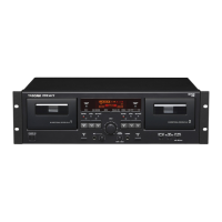
Describes the functions of controls and features on the front panel of the cassette deck.
Lists and describes the rear panel connectors for external devices and signals.
Introduces the control section of the circuit description, focusing on the system control IC.
Details the system control IC, including pin assignments and its function in controlling deck operations.
Presents the block diagram for the system control IC, illustrating signal flow and logic.
Shows a table detailing input signals, output signals, and resulting operating modes of the control IC.
Summarizes how the deck transitions between different modes based on input signals.
Explains how the deck handles simultaneous input signals and prioritizes modes.
Provides a table of input and output voltage levels for various signal types.
Details the input and output circuits for the system control IC.
Explains the initial reset circuit that ensures the deck starts in a stop mode upon power-on.
Details the output control circuit that prevents erroneous signals during power-off.
Describes the solenoid drive circuits and the functions of the solenoids.
Describes the functions of the three solenoids and their mechanical roles.
Explains the electrical circuit for driving the fast solenoid, including its flashing circuit operation.
Details the drive circuit for the head base solenoid, noting its similarity to the fast solenoid circuit.
Describes the pinch roller solenoid drive circuit, including power delay and reproduce delay circuits.
Explains the reproduce delay circuit and its role in timing solenoid operations.
Explains the reel motor drive circuit and its operation in different modes.
Explains how the reel motor rotates in different modes and drives the reel disks via pulleys.
Details the operation of the reel motor drive circuit during the reproduce mode.
Explains the reel motor drive circuit operation during the rewind mode.
Describes the reel motor drive circuit operation during the fast-forward mode.
Explains the capstan motor operation, its torque transmission, and speed selection.
Details the circuit that detects the end of the tape using a reed switch and ring magnet.
Explains the memory circuit's function with the tape counter and memory switch.
Details the power supply circuits, including the main regulator.
Describes the main voltage regulator circuit and its components.
Explains the feedback process that stabilizes the output voltage of the main regulator.
Details the overall DC power supply system, including minor regulated power supplies.
Briefly describes deck operations in reproduce, pause, fast-forward, and rewind modes.
Explains the deck's operation in reproduce mode, divided into head base and pinch roller subsystems.
Describes the deck's operation in pause mode, referencing head base and indicator subsystems.
Details the deck's operation in fast-forward mode, split into fast-forward and fast subsystems.
Explains the deck's operation in rewind mode, divided into rewind and fast subsystems.
Explains the muting circuits that prevent unwanted noise during operation.
Explains the power muting circuit that prevents noise during power on/off transitions.
Describes the reproduce muting circuit that mutes the equalizer amplifier in non-reproduce modes.
Explains the record muting circuit and its operation during record/reproduce and REC/MUTE modes.
Reproduce circuit including equalizer amplifier, bias trap, and level adjustments.
Explains the monitor circuit's function for output, headphone, and meter signals.
Explains how the monitor signal is output and controlled.
Describes the headphone amplifier and its level control.
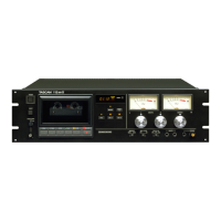
Introduces the meter circuit, including sensitivity switching for adjustments.
Explains the peak indicator circuit, its components, and operation with a timing diagram.
Details the record circuits, including line inputs and amplifiers.
Details the line input circuits (Line 1 and Line 2) and their connection to the Dolby encoder.
Explains the line amplifier, including its recording level adjustment and temperature compensation.
Describes the record amplifier, its equalization characteristics, and its connection to the record head.
Explains the Dolby HX system for improved recording performance.
Explains tape bias characteristics and how they affect recording quality and frequency response.
Details the Dolby HX system's operation, including automatic bias and equalization control.
Explains how the Dolby HX system controls bias based on input signal characteristics.
Describes how the Dolby HX system controls recording equalization to optimize tape performance.
Details the circuits controlling recording bias and equalization.
Explains the circuit that generates a control signal based on high-frequency input components.
Describes the circuit that varies bias based on the control signal, affecting the bias oscillator.
Details the variable equalizer circuit that adjusts cutoff time constant based on the control signal.
Lists parts for the first exploded view, detailing covers, connectors, and brackets.
Lists parts for the second exploded view, covering PCBs, switches, and miscellaneous items.
Lists parts for the third exploded view, focusing on mechanical assemblies like motors and solenoids.
Lists parts for the fourth exploded view, detailing smaller mechanical components and PCBs.
Provides instructions for positioning the head base plate to eliminate clearance.
Details the procedure for adjusting the clearance of microswitch (A).
Outlines the steps for adjusting the clearance of microswitch (B).
Explains how to adjust the thrust of the capstan shaft for proper tape travel.
Describes how to adjust takeup torque for stable tape travel and speed.
Details the procedure for measuring and adjusting fast forward and rewind torque.
Explains how to adjust pinch roller pressure for stable tape travel and speed.
Provides instructions for measuring and adjusting tape speed using a frequency counter.
Explains how to measure wow and flutter using dedicated test tapes and meters.
Describes how to check and adjust the record/reproduce head azimuth for optimal phase difference.
Details the procedure for setting the reproduce output level using test tapes and semi-fixed resistors.
Explains how to set the VU meter reading to the correct level using test tapes and resistors.
Guides on checking and adjusting the reproduce frequency response with test tapes and EQ switches.
Provides detailed steps for adjusting bias settings for different tape types using test tapes and switches.
Outlines the procedure for setting the record level, including input and output adjustments.
Describes how to check the overall frequency response after setting levels and bias.
Explains how to measure the signal-to-noise ratio and the acceptable values.
Details how to measure the overall distortion of the recorded and reproduced signal.
Provides steps for checking the effectiveness of the tape erasure process.
Explains how to measure channel separation and the required minimum value.
Details how to adjust the peak indicator LED lighting level for proper operation.
Guides on checking the effect of the Dolby NR system by measuring level changes.
Explains how to check the Dolby HX effect by monitoring response changes.
Describes how to measure the headphones output level.
Outlines when and how to adjust the bias trap.
Provides detailed procedures for checking and calibrating bias and record levels.
Lists parts for the first exploded view, detailing covers, connectors, and brackets.
Lists parts for the second exploded view, covering PCBs, switches, and miscellaneous items.
Lists parts for the third exploded view, focusing on mechanical assemblies like motors and solenoids.
Lists parts for the fourth exploded view, detailing smaller mechanical components and PCBs.
Lists components for the power supply PCB.
Lists components for the meter amplifier PCB.
Lists components for the lever switch PCB.
Lists components for the record/play amplifier PCB, including ICs, transistors, diodes, and resistors.
Lists capacitor part numbers and specifications.
Lists thermistor part numbers and specifications.
Lists variable resistor part numbers and specifications.
Lists coil part numbers and specifications.
Lists miscellaneous parts (connectors, filters).
Component list for the joint PCB.
Component list for the power supply PCB.
Lists capacitor part numbers and specifications.
Lists variable resistor part numbers and specifications.
Component list for the meter amplifier PCB.
Component list for the input/output terminal PCB.
Component list for the memory switch PCB.
Component list for the remote connector PCB.
Component list for the reed switch PCB.
| Tape Speed | 4.76 cm/s |
|---|---|
| Track System | 4-track, 2-channel stereo |
| Total Harmonic Distortion | 0.8% |
| Motor | DC servo motor |
| Wow and Flutter | 0.04% WRMS |
| Input | Line: 50mV |