•••
•••
[
122
7.
RECORD/REPRODUCE AMPLIFIER CHECKS
AND
ADJUSTMENTS
Remove the top cover
by
unscrewing the
scrElWS
securing it. When the
top
cover
is
removed, the
record/reproduce
amplifier
PCB
ASSY
can
be
seen.
When adjusting the azimuth
of
the record/
reproduce head, remove the cassette holder
door
cover.
The
following
points should
be
observed before
starting the record/reproduce
amplifier
checks
or
adjustments.
* Before adjusting the amplifier, the
erase
head,
record/reproduce head and tape path shou I d
be
demagnetized and cleaned
with
cleaning
fluid.
*
Adjust
the
left
channel first, then the
right
channel. In the
circuit
diagrams, 100-series
numbers refer
to
left
channel components and
200-series numbers refer
to
right
channel
components. For example, R180
is
a
left
channel resistor
while
R280
is
the equivalent
right
channel resistor.
Left
channel/Right channel components
are
shown
as
R
180/R280.
* 0
dB
= 1 V
* Unless otherwise specified, set the switches
as
follows:
Switches
Positions
MONITOR
TAPE
DDLBY
NR
OUT
INPUT
LlNElor2
SPEED
STANDARD
EQ
METAL
BIAS
METAL
MEMORY
OFF
CAL
PRESET
*
If
characteristics such
as
frequency response
and crosstalk
are
found
to
be
unsatisfactory,
it
is
necessary
to
check and adjust the
azimuth
of
the record/reproduce head
first
prior
to
performing
amplifier
adjustment.
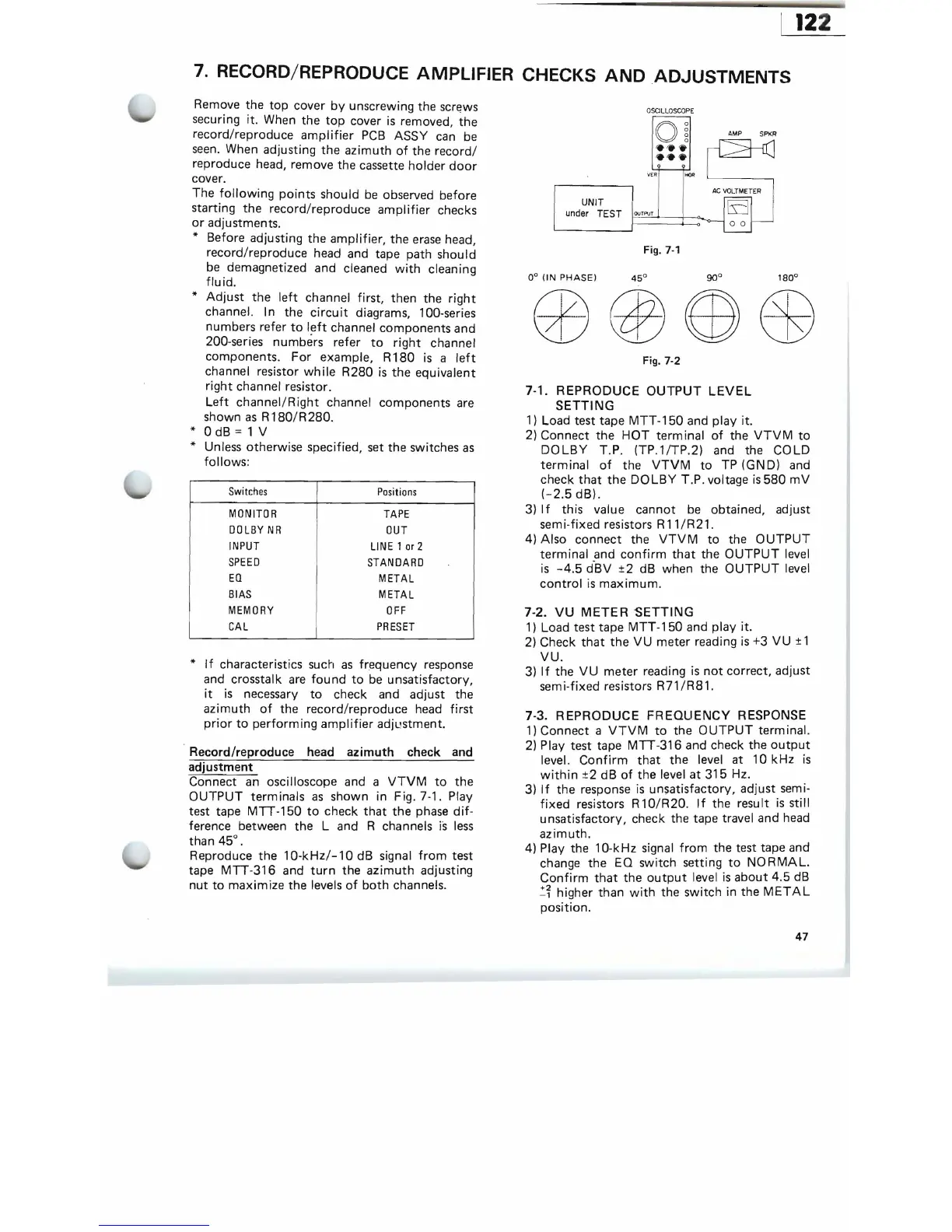
. Record/reproduce head
azimuth
check and
adjustment
Connect
an
oscilloscope and a
VTVM
to
the
OUTPUT
terminals
as
shown in Fig. 7-1. Play
test tape
MTT-150
to
check
that
the
phase
dif-
ference between the
Land
R channels
is
less
than
45°.
Reproduce the
10-kHz/-10dB
signal
from
test
tape
MTT-316
and
turn
the
azimuth
adjusting
nut
to
maximize the levels
of
both
channels.
O
SCILL
OS
COPE
O
~
VER
HOR
AMP SPKR
AC
VOLTMETER
EJ
00
UNIT
under
TEST
F
OU~TF'VT==t
~
o-1
I--
Fig.
7-1
0°
(IN
PHASE)
Fig. 7-2
7-1. REPRODUCE
OUTPUT
LEVEL
SETTING
1)
Load test tape
MTT
-150 and play it.
2)
Connect the
HOT
terminal
of
the
VTVM
to
DOLBY
T.
P.
(TP.1/TP.2) and the COLD
terminal
of
the
VTVM
to
TP (GND) and
check
that
the
DOLBY
T.P. voltage
is
580
mV
(-2.5
dB).
3)
If
this value cannot
be
obtained, adjust
sem
i-fixed resistors R
11
/R21.
4) Also connect the
VTVM
to
the
OUTPUT
terminal and
confirm
that
the
OUTPUT
level
is
-4.5
d-BV ±2 dB when the
OUTPUT
level
control
is
maximum.
7-2.
VU
METER
SETTING
1)
Load test tape
MTT-150
and play it.
2)
Check
that
the
VU
meter reading
is
+3 VU ± 1
VU.
3)
If
the
VU
meter reading
is
not
correct, adjust
semi-fixed resistors
R71/R81.
7-3. REPRODUCE
FREQUENCY
RESPONSE
1)
Connect a
VTVM
to
the
OUTPUT
term ina!.
2)
Play test tape
MTT-316
and check the
output
level.
Confirm
that
the level at
10kHz
is
within
±2 dB
of
the level
at
315 Hz.
3)
If
the response
is
unsatisfactory, adjust semi-
fixed
resistors R 1
O/R
20. I f the
resu
It
is
sti
II
unsatisfactory, check the tape travel and head
azimuth.
4) Play the 10-kHz signal
from
the test tape and
change the EQ switch setting
to
NO
RMAL.
Confirm
that
the
output
level
is
about 4.5
dB
~~
higher than
with
the switch in the
METAL
position.
47