122
OSCILLOSCOPE
OSCILLATOR
AMP
SPKR
flC.
VOLTMETER
UNIT
under
TEST
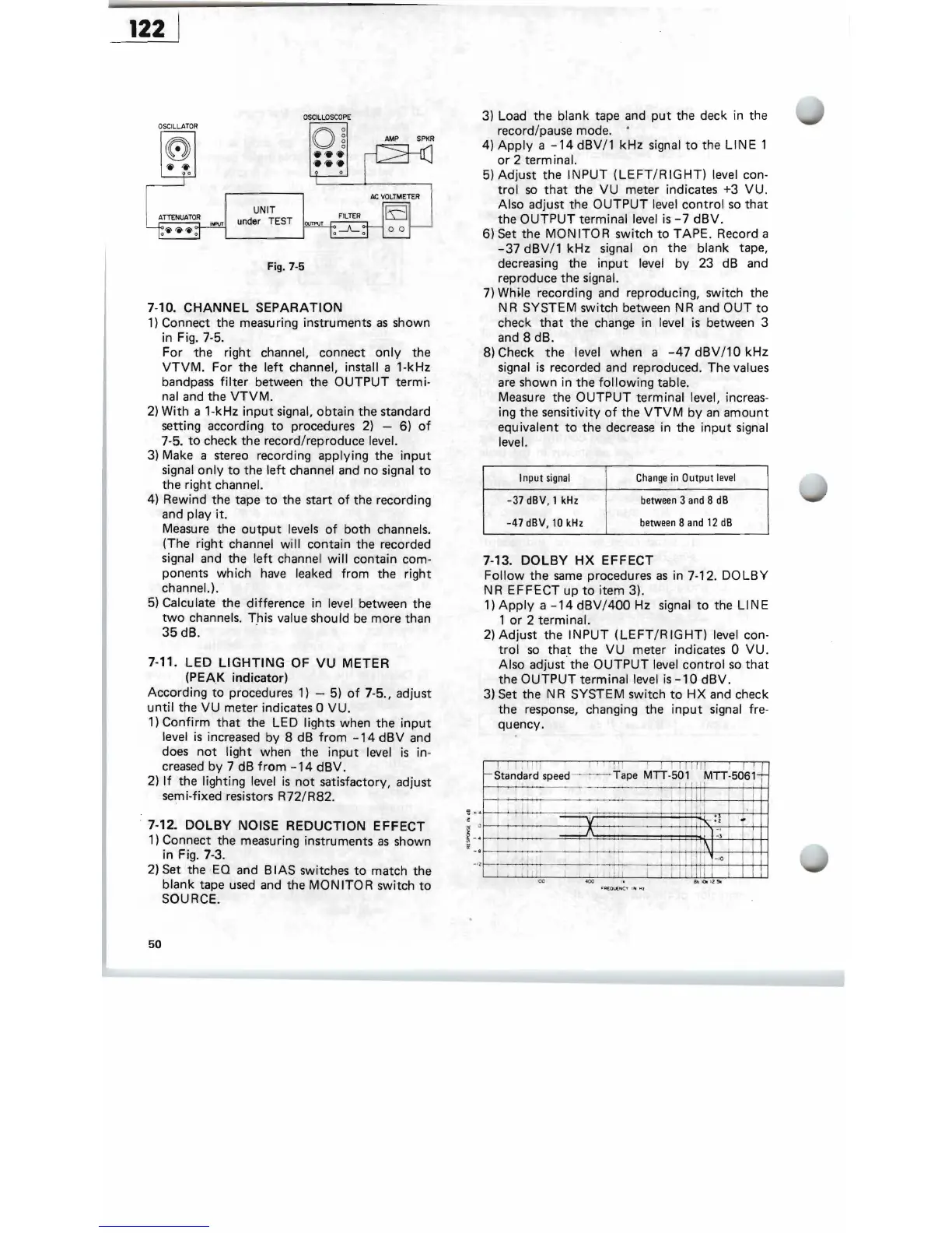
Fig. 7-5
7-10.
CHANNEL
SEPARATION
1)
Connect the
measu
ring instru ments
as
shown
in Fig. 7-5.
For the right channel, connect
only
the
VTVM.
For the
left
channel, install a 1-kHz
bandpass
filter
between the OUTPUT termi·
nal and the
VTVM.
2)
With a 1-kHz
input
signal, obtain the standard
setting according
to
procedures
2)
- 6)
of
7-5.
to
check the record/reproduce level.
3)
Make a stereo recording applying the
input
signal
only
to
the
left
channel and no signal
to
the right channel.
4)
Rewind the tape
to
the start
of
the recording
and play
it.
Measure the
output
,levels
of
both channels.
(The right channel will contain the recorded
signal and the
left
channel wil'l contain com-
ponents wh ich
have
leaked from the right
channeL).
5)
Calculate the difference in level, between the
two
channels. This value should
be
more than
35dB.
7-11.
LED
LIGHTING
OF
VU
METER
(PEAK indicator)
According
to
procedures
1)
- 5)
of
7-5., adjust
until
the
VU
meter indicates 0 VU.
1)
Confirm
that
the LED lights when the
input
level
is
increased by 8 dB
from
-14
dBV
and
does
not
light
when the
input
level
is
in-
creased
by 7 dB
from
-14
dBV.
2)
If
the lighting level
is
not
satisfactory, adjust
semi-fixed resistors R72/R82.
7-12.
DOLBY
NOISE REDUCTION EFFECT
1)
Connect the measuring instruments
as
shown
in Fig. 7-3.
2)
Set the
EQ
and B
lAS
switches
to
match the
blank tape
used
and
the
MONITOR
switch
to
SOURCE.
50
3) Load the blank tape
and
put
the deck in the
record/pause mode.
4)
Apply
a
-14
dBV
/1
kHz
signal
to
the LI N E 1
or
2 term inal.
5)
Adjust the INPUT
(LEFT/RIGHT)
level con-
trol
so
that
the
VU
meter indicates +3 VU.
Also adjust the
OUTPUT
level control
so
that
the
OUTPUT
terminal level
is
-7
dBV.
6) Set the
MONITOR
switch
to
TAPE. Record a
-37
dBV/1 kHz signal on the blank tape,
decreasing the
input
level by 23 dB and
reproduce the signal.
7)
Wh~le
recording and reproducing, switch the
N R SYSTEM switch between N R and
OUT
to
check
that
the change in level
is
between 3
and 8 dB.
8) Check
the
level when a
-47
dBV
/10
kHz
signal
is
recorded and reproduced. The values
are
shown in the
following
table.
Measure the
OUTPUT
terminal level, increas-
ing the sensitivity
of
the
VTVM
by
an
amount
equ
ivalent
to
the decrease in the
input
signal
level.
Input
signal
Change
in
Output
level
-37 dBV. 1
kHz
between
3
and
8
dB
-47 dBV,
10
kHz
between
8
and
12
dB
7-13.
DOLBY
HX
EFFECT
Follow
the
same
procedures
as
in 7-12.
DO
LBY
NR
EFFECT
up
to
item 3).
1)
Apply
a
-14
dBV/400
Hz signal
to
the
LINE
1
or
2 terminal.
2)
Adjust the INPUT
(LEFT/RIGHT)
level con-
trol
so
tha.t the
VU
meter indicates 0
VU.
Also adjust the
OUTPUT
level
control
so
that
the
OUTPUT
terminal level
is
-10
dBV.
3) Set the N R SYSTEM switch
to
HX
and check
the response, changing the
input
signal fre-
quency.
i
i'
, . .
..!.
I I, I " l 1
.1
t-
Standard speed - -- - Tape MTT-501
MTT.5~61
1 _ _ .
,
~
,
~
,
-
j il l
I
.
I
----VV .
'
.1
.
,
- .,
,.
..
~
,
-,
-,
z
r-
-
II
I i\
11
"0
,
,
11
co
.
'
..1
1
~
ulil
,