•••
•••
122
7-4.
BIAS
SETTING
ADJUSTMENT
Before adjusting the bias setting :
a.
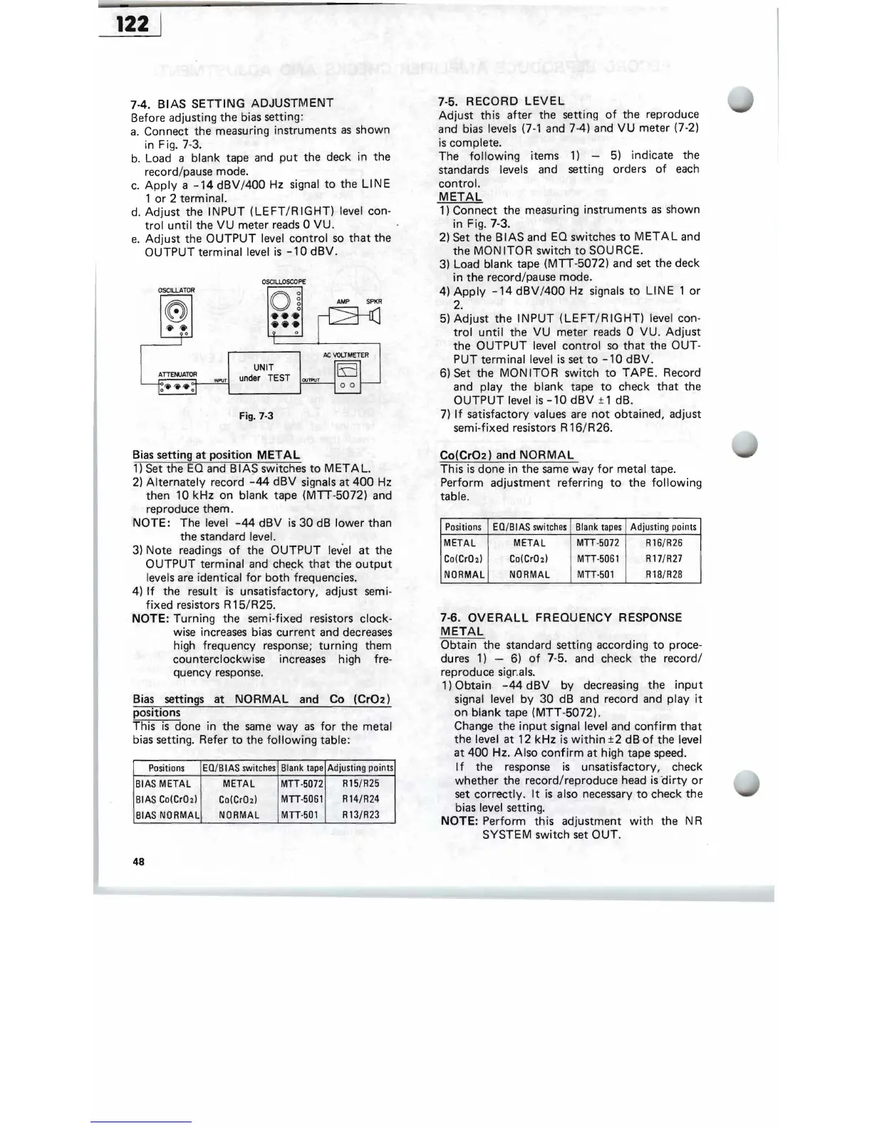
Connect the measuring instruments
as
shown
in Fig. 7-3.
b.
Load a blank tape and
put
the deck in the
record/pause mode.
c.
Apply
a
-14
dBV/400
Hz signal
to
the
LINE
1
or
2 terminal.
d.
Adjust
the
INPUT
(LEFT/RIGHT)
level con-
trol
until
the
VU
meter reads 0
VU.
e.
Adjust
the
OUTPUT
level
control
so
that
the
OUTPUT
terminal level
is
-10
dBV.
OSCILLOSCOPE
OSCILLATOR
'0
O
~
AMP
SPKR
'i''i'
0
~':::=,*-_~
/Ie
VOLTMETER
UNIT
"'
P\J!!!.j'
under
TEST
OJ"""
o 0
Fig. 7-3
Bias setting
at
position
METAL
1)
Set the
EO
and B I AS switches
to
MET
A
L.
2)
Al
,ternately record
-44
dBV
signals at
400
Hz
then 10
kHz
on blank tape (MTT-5072) and
reproduce them.
NOTE:
The level
-44
dBV
is
30
dB
lower than
the standard level.
3)
Note readings
of
the
OUTPUT
lev'
el
at
the
OUTPUT
terminal and
che~k
that
the
output
levels are identical
for
both
frequencies.
4)
If
the resul,t
is
unsatisfactory, adjust semi-
fixed
resistors R
15/R25.
NOTE: Turning the semi-fixed resistors clock-
wise increases bias
current
and decreases
high frequency response;
turning
them
counterclockwise increases high fre-
quency response.
Bias settings at
NORMAL
and Co
(Cr02)
positions
This
is
done in the
same
way
as
for
the metal
bias setting. Refer
to
the
following
table:
Blank
tape
Adjusting
points
Positions
EO/BIAS
switches
L
R15/R25
METAL
MTT·5072
il
BIAS
METAL
R l4/R24
MIT·5061
Co(CrOz)
I
~IAS
Co(CrOz)
NORMAL
MIT·501
R13/R23
BIAS
N'
ORMAL
48
7-5.
RECORD
LEVEL
Adjust
this
after
the setting
of
the reproduce
and b
ias
levels
(7-1
and 7-4) and
VU
meter (7-2)
is
complete.
The
following
items
1)
-
5)
indicate the
standards levels and setting orders
of
each
control.
METAL
1)
Connect the measuring instruments
as
shown
in Fig. 7-3.
2)
Set the
BIAS
and EO switches
to
METAL
and
the
MONITOR
switch
to
SOURCE.
3)
Load blank tape
(MTI-5072)
and
set
the deck
in the record/pause mode.
4)
Apply
-14
dBV/400
Hz signals
to
LINE
1
or
2 .
5)
Adjust
the
INPUT
(LEFT/RIGHT)
level con-
trol
until
the
VU
meter
reads
0
VU
.
Adjust
the
OUTPUT
level
control
so
that
the OUT-
PUT terminal level
is
set
to
-10
dBV.
6) Set the
MONITOR
switch
to
TAPE.
Record
and play the blank tape
to
check
that
the
OUTPUT
level
is
-10
dBV
± 1 dB.
7)
If
satisfactory values
are
not
obtained, adjust
semi-fixed resistors R 16/R26.
Co(Cr02)
and
NORMAL
This
is
done in the
same
way
for
metal tape.
Perform adjustment referring
to
the
following
table.
Positions
EO/BIAS
switches
Blank
tapes
Adjusting
po
i
nts
METAL METAL
MTT·5072
R16/R26
Co(CrO
z)
Co(CrOz)
MIT·5061
R17/R27
NORMAL NORMAL
MTT-50l
R18/R28
7-6.
OVERALL
FREQUENCY
RESPONSE
METAL
Obtain the standard setting according
to
proce-
dures
1)
- 6)
of
7-5. and check the record/
reproduce sigr.als.
1) Obtain
-44
dBV
by
decreasing the
input
signal level
by
30
dB and record and play
it
on
blank
tape
(MTT
-5072).
Change the
input
signal level and
confirm
that
the level at 12
kHz
is
within
±2
dB
of
the level
at
400
Hz. Also
confirm
at
high tape speed.
I f the response
is
unsatisfactory, check
whether the record/reproduce head
is
-
dirty
or
set
correctly.
It
is
also necessary
to
check the
bias level setting.
NOTE: Perform this adjustment
with
the N R
SYSTEM switch set
OUT
.